Page 48
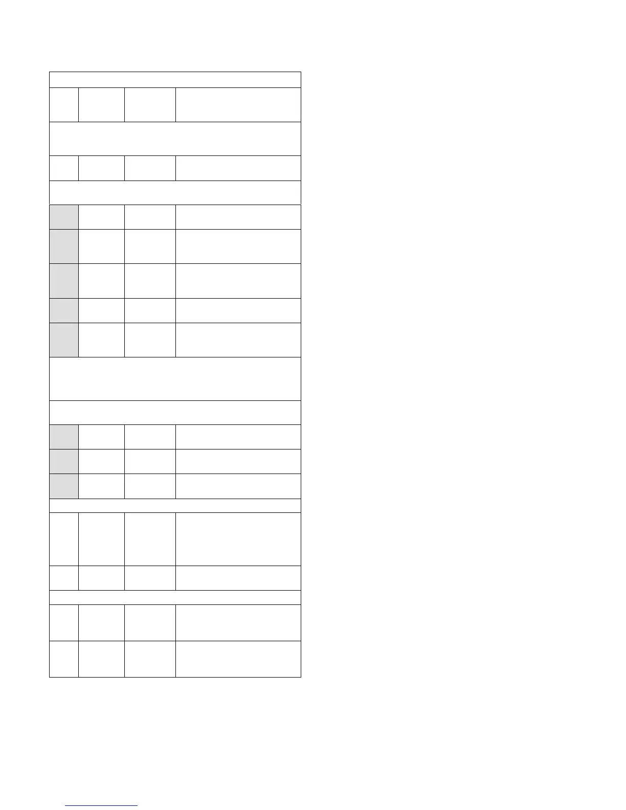
TABLE 41
580684
LGH/LCH 122U4E (2-Compressor) Staged Direct Drive
Para
met
er
Factory
Setting
Field
Setting
Description
Note: Any changes to Smoke CFM setting must be adjusted
before the other CFM settings. Use SETTINGS > RTU OPTIONS
> EDIT PARAMETERS
12
4000
CFM
CFM
Blower CFM during smoke
detection.
SETUP > TEST & BALANCE (can also use SETTINGS > RTU
OPTIONS > BLOWER > SPEEDS)
4000
CFM
CFM
Blower CFM during heating.
4000
CFM
CFM
Blower CFM during high speed
cooling (2 compressor)
operation.
2600
CFM
CFM
Blower CFM during low speed
cooling (1 compressor)
operation.
4000
CFM
CFM
Blower CFM during ventilation.
1425
RPM
RPM*
Adjust RPM based on unit static
and blower tables to reach tar
get CFM.
*Once all four blower settings are entered, the target (highest of the
heating and cooling settings) CFM will be displayed. Once the RPM
is saved for the target CFM, all other blower RPM values are set by
the Unit Controller according to the field CFM setting..
SETUP > TEST & BALANCE (can also use SETTINGS > RTU
OPTIONS > DAMPER)
0% %
Damper min. position during
LOW blower operation.
0% %
Damper min. position during
HIGH blower operation.
50% %
Min. damper % for stage 1 pow
er exhaust operation.
SETTINGS > RTU OPTIONS > EDIT PARAMETERS
29 101% %Open
Damper minimum position during
G blower operation. (Setting para
meter 29 to “101” disables para
meter 29 and passes control to
parameter 9 or 132)
216 5% %
Deadband % for stage 1 power
exhaust operation.
SETTINGS > RTU OPTIONS > EDIT PARAMETER
85 40°F °F
Compressor 1 low temp lockout.
Settings lower than 40°F could
void warranty.
86 40°F °F
Compressor 2 low temp lockout.
Settings lower than 40°F could
void warranty.
 Loading...


