Page 100
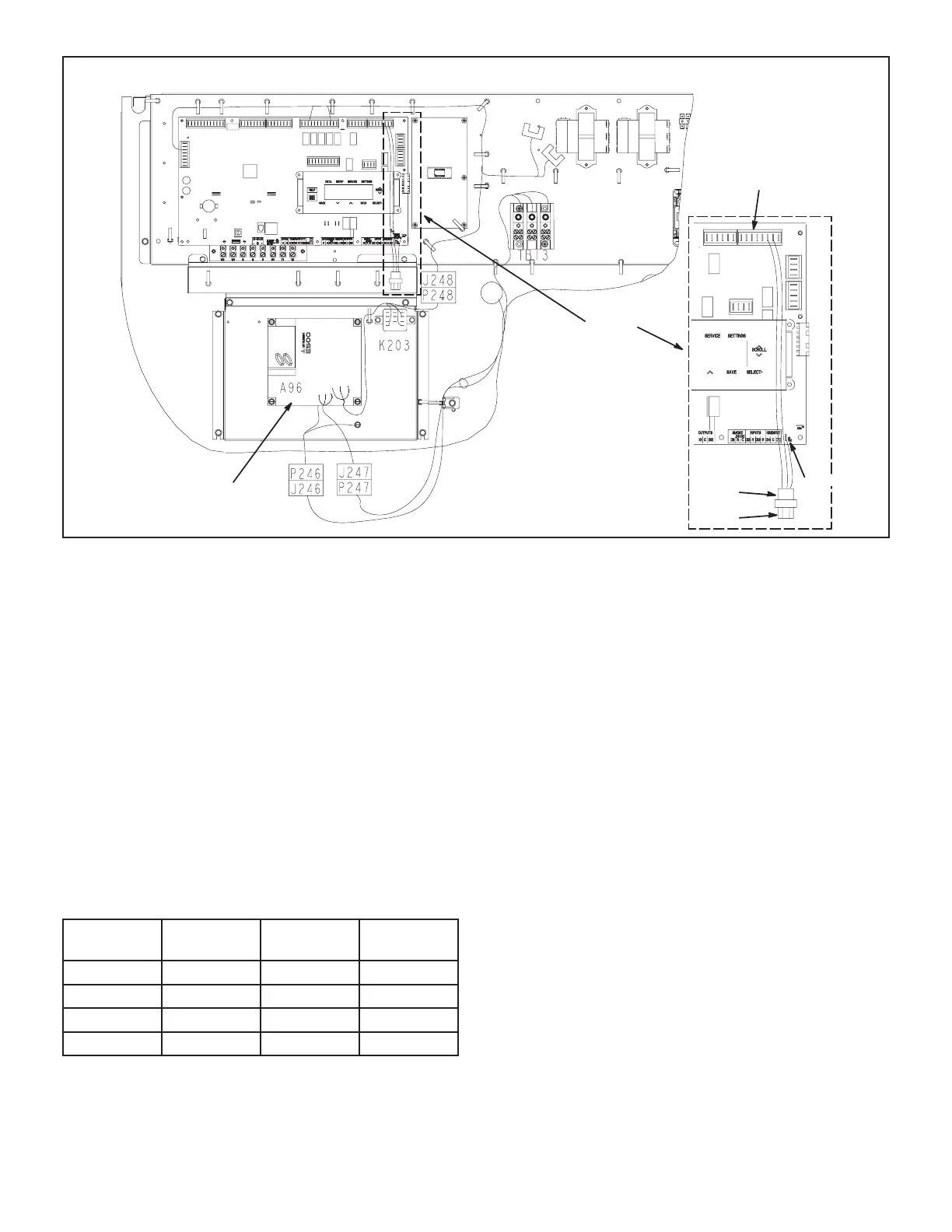
SUPPLY AIR VARIABLE FREQUENCY DRIVE
A55 UNIT
CONTROLLER
A96
SUPPLY AIR
VFD
DETAIL A
P300
J300
24V
P267
FIGURE 41
Note - The Unit Controller will lock-out the unit for
5 minutes if static pressure exceeds 2.0”w.c. for 20
seconds. The Unit Controller will permanently shut
down the unit after three occurrences. See Unit
Controller parameters 110, 42, and 43 to adjust
default values.
8 - If the desired CFM cannot be met with current
pulley setup, refer to the Blower Operation and
Adjustments section to adjust CFM.
B-Unit Operation
Use the Unit Controller to check unit mechanical opera-
tion. See the Service - Test section of the Unit Controller
manual.
TABLE 44
RECORD ADJUSTED SETPOINTS
Parameter
Setpoint
Description
Setpoint
“w.c.
Display
Setting
386 Smoke
387 Ventilation
388 Heating
Cooling
C-Supply Air VFD Bypass (Optional)
IMPORTANT - All dampers must be open to prevent
damage to duct work and dampers.
1 -
2 -
3 -
4 -
5 - Locate VFD control relay K203 on the lower control
6 - Locate wires labeled K203-A and K203-B in area
7 - Locate wires labeled K3-A and K3-B coming from
K3 blower relay. Connect to K203-A to K3-A and
K203-B to K3-B.
8 - Restore power to unit. Blower will operate in
constant air volume (CAV) mode.
Check the indoor blower motor nameplate for full
load amperage (FLA) value. Measure the amp
readings from the indoor blower motor operating
in bypass mode. If measured amps are higher
than nameplate FLA value, decrease the CFM
by opening (turning counterclockwise) the motor
maximum number of pulley turns as shown in table
5.
 Loading...


