C-Zone Sensor (4 Clg. Stages), 4-Compressor Units
1-Economizer With Outdoor Air Suitable Y1 Demand -
Blower Cooling Low
Dampers modulate
Y2 Demand -
Blower Cooling High
Dampers Modulate
156, 180H, 210, 240H, 300S - If dampers are at maximum
open for three minutes, compressor 1 is energized and
blower stays on cooling high.
180U, 240U, 300U - If dampers are at maximum open for
three minutes, two compressors (one from each circuit)
are energized and blower stays on cooling high.
Y3 Demand -
Compressors 1 and 2 On
180U, 240U, 300U - Two Compressors On
(one from each circuit)
Blower Cooling High
Dampers Maximum Open
Y4 Demand -
All Compressors On
Blower Cooling High
Dampers Maximum Open
2-No Economizer or Outdoor Air Not Suitable
Y1 Demand -
Compressor 1 On
180U, 240U, 300U - Two Compressors On
(one from each circuit)
Blower Cooling Low
Y2 Demand -
Compressors 1 and 2 On
180U, 240U, 300U - Two Compressors On
(one from each circuit)
Blower Cooling Medium Low
Y3 Demand -
Compressors 1, 2 and 3 On
180U, 240U, 300U, any three compressors are On
Blower Cooling Medium High
Y4 Demand -
All Compressors On
Blower Cooling High
X--VAV System
Refer to the installation instructions for additional informa-
tion and available replacements.
Units may contain an optional supply air blower equipped
supply air CFM.
-
NOTE - Units equipped a Variable Frequency Drive (VFD)
are designed to operate on balanced, three-phase power.
Operating units on unbalanced three-phase power will re-
duce the reliability of all electrical components in the unit.
Unbalanced power is a result of the power delivery system
supplied by the local utility company. Factory-installed in-
verters are sized to drive blower motors with an equiva-
lent current rating using balanced three-phase power. If
unbalanced three-phase power is supplied; the installer
must replace the existing factory-installed inverter with an
inverter that has a higher current rating to allow for the
imbalance.
A-Start-Up
1 - A pressure transducer (A30) is shipped in a box
in the blower compartment. Install the transducer
according to manufacturer's instructions.
Note - Make sure the transducer is installed in the
main duct at least 2/3 of the distance away from the
unit.
2 - Two twisted pairs of shielded cable must be used to
P300 connector is hanging in the control box.
3 - Open all zone dampers and/or boxes.
4 -
5 - Use the Unit Controller to calibrate the blower CFM.
Select the SETUP->TEST & BALANCE->BLOWER
menu to start the blower. The Unit Controller
will display the percent of blower speed. Adjust
6 - Press SAVE to display the current static pressure. If
press SAVE again to set the setpoint. If the static
adjust the pressure and press SAVE to set the
setpoint.
7 - Record new setpoints in table 43.
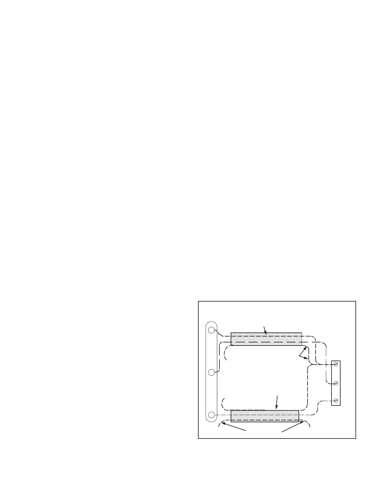
PRESSURE TRANSDUCER WIRING
TWISTED
PAIR
UNUSED WIRE
DRAIN
NOT
CONNECTED
NOT
CONNECTED
TWISTED
PAIR
A30
+S
_
+
J300
1
2
3
FIGURE 40
 Loading...


