Page 115
Staged-Blower UNITS - WITH BYPASS
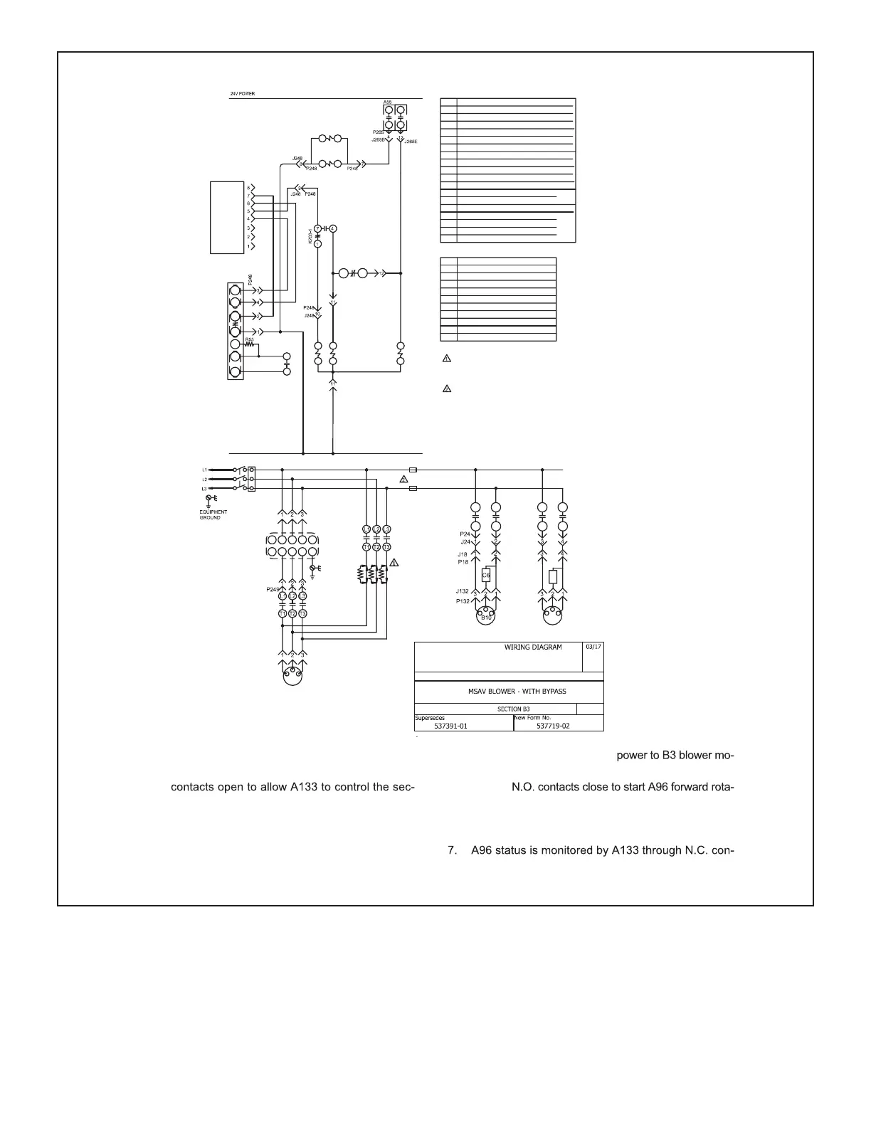
1. A55 energizes K202 and K203 relay coils.
2. K203-1 N.O. contacts close and K203-3 N.C.
ond stage power exhaust relay K231 coil through
pin #5. K231-1 and -2 N.O. contacts will close to
start the second power exhaust fan B11 when
A133 energizes K231 coil.
3. K203-1 N.C. contacts open to de-energize K3
relay coil. K3 contacts open to interrupt power to
B3 blower motor through K3 N.O. relay contacts.
4. K202 contacts close to allow
tor from A96.
5. K203-2
tion signal STF.
6. Blower B3 speed is controlled by a 0-10VDC signal
from A133 AO1 to A96 terminal 2.
tacts B-C on A96.
COOLING
REV. 0
S42 USED ON M−VOLT UNITS AND UNITS WITH
HIGH EFFICIENCY MOTORS AND MOTORS
LESS INTERNAL OVERLOAD PROTECTION
S48
B11
C8
F6
F6
P133
J133
TB13
F6 FUSES ARE USED ON 240/300 Y−VOLT
UNITS WITH FACTORY INSTALLED
POWER EXHAUST
F6 FUSES ARE USED ON ALL Y−VOLT
UNITS WITH FIELD INSTALLED POWER
EXHAUST
RST
WV
U
G
G
A96
J246
P246
J247
K3
K231-1
7
4
K231-2
9
6
S42
K202
J249
P247
B3
P24
J24
P18
J18
KEY COMPONENT
A55
PANEL, MAIN CONTROL
A96
CONTROL, INVERTER
A133
CONTROL, GENERAL PURPOSE
B3
MOTOR, BLOWER
B10
MOTOR, EXHAUST FAN 1
B11
MOTOR, EXHAUST FAN 2
C6
CAPACITOR, EXHAUST FAN 1
C8
CAPACITOR, EXHAUST FAN 2
F6
FUSE, EXHAUST FAN
18 POWER EXHAUST HARNESS
24
POWER, RELAY TO EXHAUST FANS
132POWER TO EXHAUST FAN MOTOR 1
133POWER TO EXHAUST FAN MOTOR 2
194
GP CONTROL INPUT, OUTPUT
246POWER TO VFD
247
POWER, VFD TO MTR
265A55 TO CONTACTORS & RELAYS
K65
RELAY, EXHAUST FAN
K203
RELAY, INVERTER START FWD ROTATION
S48
SWITCH, DISCONNECT
TB13
TERMINAL STRIP, POWER DISTRIBUTION
248VFD CONTROL
J/P JACK/PLUG DESCRIPTION
K202
CONTACTOR, VFD POWER TO MOTOR
K231
RELAY, EXHAUST FAN 2
K3
CONTACTOR, BLOWER
249
POWER, CONTACTOR BYPASS
K65
A
B
P265
J265E
K231
A
B
24V COMMON
K203-2
9
6
STF
SD
K203
A
B
2
A96
5
C
B
J248
J248
K202
A
B
K3
A
B
P248
J248
K203-3
8
2
P248
J248
S42
SWITCH, OVERLOAD RELAY BLWR MOTOR
J259
(ODF)PWM 2
(ODF)PWM 3
COM
(IDB)PWM 1/VO
RELAY
COM
FB
20V
A55
K65-1
7
4
K65-2
9
6
PC
R55
RESISTOR, VFD LOADING, A96
 Loading...


