Page 46
10-Spark Electrodes
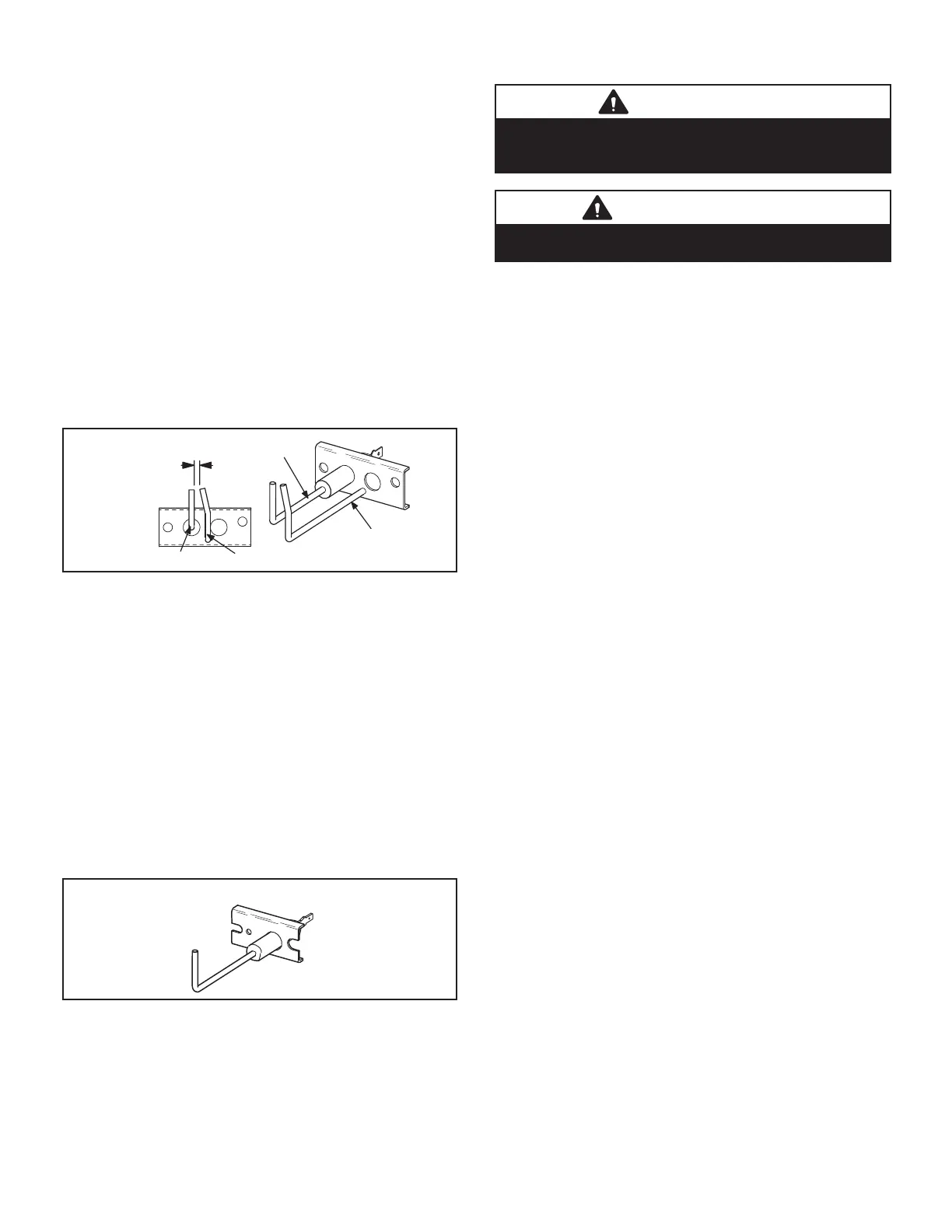
An electrode assembly is used for ignition spark. Two
identical electrodes are used (one for each gas heat sec-
tion). The electrode is mounted through holes on the left
-most end of the burner support. The electrode tip pro-
electrode assembly is fastened to burner supports and
can be removed for service without removing any part of
the burners.
During ignition, spark travels through the spark electrode
burner to burner until all are lit.
The spark electrode is connected to the ignition control
by a 8 mm silicone-insulated stranded high voltage wire.
The wire uses 1/4” (6.35 mm)female quick connect on the
electrode end and female spark plug-type terminal on the
ignition control end.
NOTE- IN ORDER TO MAXIMIZE SPARK ENERGY TO
ELECTRODE, HIGH VOLTAGE WIRE SHOULD TOUCH
UNIT CABINET AS LITTLE AS POSSIBLE.
GROUND
ELECTRODE
GROUND
ELECTRODE
.125” ± .015”
(3.2 mm ± .4 mm)
FIGURE 24
11-Flame Sensors
-
er support. The sensor is mounted through a hole in the
-
lope of the right most burner. The sensor assembly is fas-
tened to burner supports and can be removed for service
without removing any part of the burners.
-
passed along the ground electrode (located on the spark
-
trode. The ignition control allows the gas valve to stay
FIGURE 25
II-PLACEMENT AND INSTALLATION
Make sure the unit is installed in accordance with the in-
stallation instructions and all applicable codes. See ac-
cessories section for conditions requiring use of the op-
tional roof mounting frame.
III-CHARGING
WARNING
Refrigerant can be harmful if it is inhaled. Refrigerant
must be used and recovered responsibly. Failure to follow
this warning may result in personal injury or death.
IMPORTANT
Units equipped with Hot Gas Re-Heat system MUST be
charged in standard cooling mode.
A-Aluminum Coils
WARNING-Do not exceed nameplate charge under
any condition.
This unit is factory charged and should require no further
adjustment. If the system requires additional refrigerant,
reclaim the charge, evacuate the system, and add re-
quired nameplate charge.
NOTE - System charging is not recommended below 60 F
(15 C). In temperatures below 60 F (15 C), the charge must
be weighed into the system.
If weighing facilities are not available, or to check the
charge, use the following procedure:
IMPORTANT - Charge unit in standard cooling mode.
1 - Make sure outdoor coil is clean. Attach gauge
manifolds and operate unit at full CFM in cooling
mode with economizer disabled until system
all outdoor air dampers are closed.
2 - Check each system separately with all stages
operating. Compare the normal operating pressures
(see tables 11 - 23) to the pressures obtained from
the gauges. Check unit components if there are
3 - Measure the outdoor ambient temperature and
the suction pressure. Refer to the appropriate
circuit charging curves to determine a target liquid
temperature.
Note - Pressures are listed for sea level applications.
4 - Use the same thermometer to accurately measure
the liquid temperature (in the outdoor section).
• If measured liquid temperature is higher than the
target liquid temperature, add refrigerant to the sys-
tem.
• If measured liquid temperature is lower than the
target liquid temperature, recover some refrigerant
from the system.
5 - Add or remove charge in increments. Allow the
system to stabilize each time refrigerant is added
or removed.
6 - Continue the process until measured liquid
temperature agrees with the target liquid
temperature. Do not go below the target liquid
temperature when adjusting charge. Note that
suction pressure can change as charge is adjusted.
7 -
ambient and a measured suction pressure of
or
in increments until measured liquid temperature
agrees with the target liquid temperature.
 Loading...


