Page 83
V- SYSTEMS SERVICE CHECKS
A-Heating System Service Checks
-
Before checking piping, check with gas company or au-
thorities having jurisdiction for local code requirements.
Refer to the LGH Installation, Operation and Maintenance
instruction for more information.
1-Gas Piping
Gas supply piping must not allow more than 0.5”W.C.
(124.3 Pa) drop in pressure between the gas meter and
the unit. Supply gas pipe must not be smaller than the
unit gas connection. Refer to installation instructions for
details.
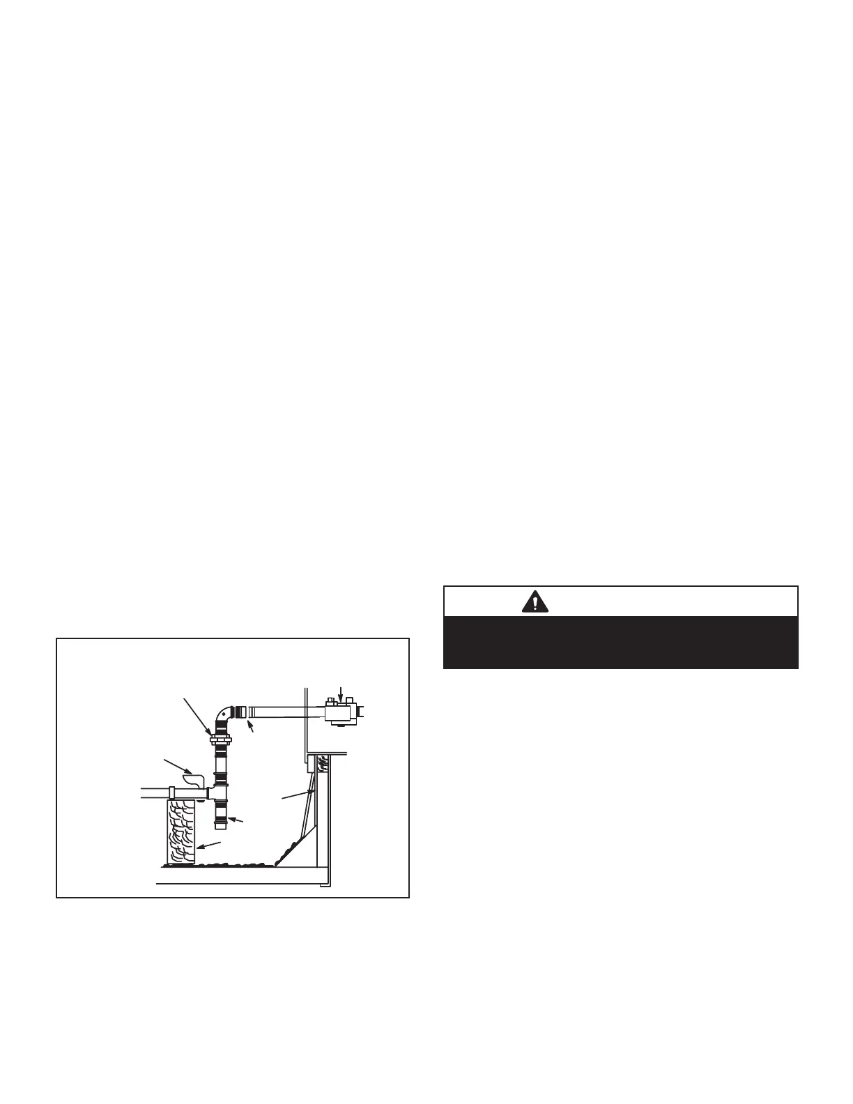
2-Testing Gas Piping
NOTE-In case emergency shutdown is required, turn o
the main manual shut-o valve and disconnect the main
power to the unit. These controls should be properly la-
beled by the installer.
When pressure testing gas lines, the gas valve must be
disconnected and isolated. Gas valves can be damaged if
subjected to more than 0.5 psig [14”W.C. (3481 Pa)]. See
When checking piping connection for gas leaks, use the
preferred means. Common kitchen detergents can cause
harmful corrosion on various metals used in gas piping.
The use of specialty Gas Leak Detector is strongly recom-
mended. It is available through Lennox under part number
31B2001. See CORP 8411-L10, for further details.
ignition to check for gas leaks.
UNIT
GROUND
JOINT UNION
MANUAL MAIN
SHUT-OFF VALVE
(REFER TO LOCAL CODES)
GAS PIPING
SUPPORT
DRIP LEG
ROOF
MOUNTING
FRAME
REFER TO INSTALLATION INSTRUCTIONS
VALVE
CAP HERE
TO ISOLATE
VALVE WHEN
PRESSURE
TESTING
LINE
FIGURE 29
3-Testing Gas Supply Pressure
When testing gas supply pressure, connect test gauge to
the inlet pressure tap located on unit gas valve GV1 and
-
mum rate (both stages energized).
Make sure the reading falls within the range of the follow-
ing values. Low pressure may result in erratic operation or
-
For natural gas units, operating pressure at the unit gas
connection must be between 4.7”W.C. and 10.5”W.C.
(1168 Pa and 2610 Pa). For L.P. gas units, operating
pressure at the unit gas connection must be between
10.8”W.C. and 13.5”W.C. (2685.3 Pa and 3356.7 Pa).
On multiple unit installations, each unit should be checked
separately while operating at maximum rate, beginning
with the one closest to the supply gas main and progress-
ing to the one furthest from the main. Multiple units should
also be tested with and without the other units operating.
Supply pressure must fall within the range listed in the
previous paragraph.
4-Check and Adjust Manifold Pressure
After line pressure has been checked and adjusted, check
manifold pressure. Move test gauge to the outlet pressure
28 for location of pressure tap on the gas valve.
The manifold pressure is factory set and should not re-
quire adjustment. If manifold pressure is incorrect and no
other source of improper manifold pressure can be found,
gas valve (manifold pressure) adjustment screw.
All gas valves are factory regulated. The gas valve should
IMPORTANT
pressure to the manometer.
Manifold Adjustment Procedure
1 - Connect test gauge to the outlet pressure tap on the
gas valve. Start the unit (call for second stage heat)
state.
2 - While waiting for the unit to stabilize, notice the
and should not lift from the burner heads. Natural
gas should burn basically blue with some clear
streaks. L.P. gas should burn mostly blue with some
clear yellow streaks.
3 -
record the manifold pressure and compare to the
values given in TABLE 10 on page 45.
 Loading...


