Page 15
Direct Drive Blower Start-Up
The supply CFM can be adjusted by changing the
percentage of motor output using the Unit Controller
settings Refer to table 3 for menu paths and default
settings.. Record any RPM% changes on the parameter
settings label located on the inside of the compressor
access panel.
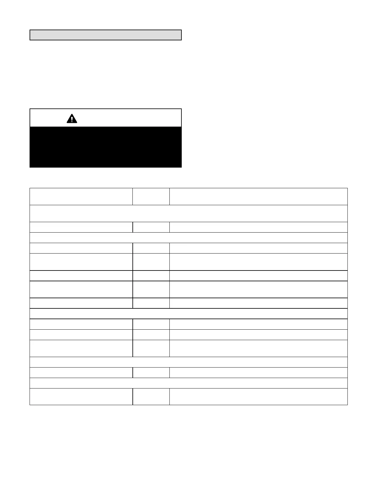
CAUTION
The BLOWER CALIBRATION process starts the in
door blower at operational speeds and moves the
economizer damper blades. Before starting this pro
cess, replace any access panels and close all unit
doors except compressor compartment door.
Blower calibration is required only on units that are newly
installed or if there is a change in the duct work or air filters
after installation. Use the mobile service app to navigate
to the SETUP>TEST & BALANCE>BLOWER menu.
After the new RPM% values are entered, select START
CALIBRATION. The blower calibration status is displayed
as a % complete. Upon successful completion, the mobile
service app will display CALIBRATION SUCCESS and go
back to the blower calibration screen.
IMPORTANT - The default value for Cooling Low motor
speed is lower than a traditional singe- or two-speed
unit. If operating the unit with a 2- or 3-stage controller
(2- or 3-stage thermostat, DDC controller, etc.), it is
recommended to increase the Cooling Low CFM
default value to a suitable level for part load cooling
(typically 60% of full load CFM).
TABLE 3
DIRECT DRIVE PARAMETER SETTINGS - 581102-01
Parameter
Field
Setting
Description
Note: Any changes to Smoke CFM setting must be adjusted before the other CFM settings. Use SETTINGS > RTU OP
TIONS > EDIT PARAMETERS = 12 for EBM, 6 for ECM
BLOWER SMOKE CFM % Percentage of RPM for blower smoke speed.
SETUP > TEST & BALANCE > BLOWER
BLOWER HEATING HIGH CFM % Percentage of RPM for blower heating high speed.
BLOWER HEATING LOW CFM %
Percentage of RPM for blower heating low speed (P volt gas heat on
ly).
BLOWER COOLING HIGH CFM % Percentage of RPM for blower cooling high speed.
BLOWER COOLING LOW CFM %
Percentage of RPM for blower cooling low speed and vent speed for
standard static blowers.
BLOWER VENTILATION CFM % Percentage of RPM for high static blower ventilation speed.
SETUP > TEST & BALANCE > DAMPER
BLOWER HIGH CFM DAMPER POS % % Minimum damper position for high speed blower operation. Default 0%.
BLOWER LOW CFM DAMPER POS % % Minimum damper position for low speed blower operation. Default 0%.
POWER EXHAUST DAMPER POS % %
Minimum damper position for low power exhaust operation. Default
50%.
SETTINGS > RTU OPTIONS > EDIT PARAMETERS = 216
POWER EXHAUST DEADBAND % % Deadband % for power exhaust operation. Default 10%.
SETTINGS > RTU OPTIONS > EDIT PARAMETERS = 10 (Applies to Thermostat Mode ONLY)
FREE COOLING STAGE-UP DELAY sec
Number of seconds to hold blower at low speed before switching to
blower at high speed. Default 300 seconds.
Installer: Record any parameter changes under “Field Setting” column. Settings need to be recorded by installer for use when Unit
Controller is replaced or reprogrammed.
 Loading...


