Page 13
LHT/LDT024, 036, 048, 060
Blower Operation and Adjustments
IMPORTANT
Three phase scroll compressors must be phased
sequentially for correct compressor and blower
rotation. Follow “COOLING START-UP” section of
installation instructions to ensure proper compres
sor and blower operation.
A-Blower Operation
Refer to the Unit Controller Setup Guide to energize
blower. Use the mobile service app menu; see RTU
MENU>COMPONENT TEST>BLOWER>START TEST
WARNING
1-Make sure that unit is installed in accordance with the
installation instructions and applicable codes.
2-Inspect all electrical wiring, both field‐ and factory‐
installed, for loose connections. Tighten as required.
3-Check to ensure that refrigerant lines do not rub against
the cabinet or against other refrigerant lines.
4-Check voltage at disconnect switch. Voltage must be
within range listed on nameplate. If not, consult power
company and have voltage condition corrected before
starting unit.
5-Make sure filters are new and in place before start‐up.
Direct-drive motor may not immediately stop when
power is interrupted to the Unit Controller.
Disconnect unit power before opening the blower
compartment. The Controller's digital inputs must be
used to shut down the blower. See Unit Controller
manual for operation sequences.
B-Determining Unit CFM
1- The following measurements must be made with air
filters in place.
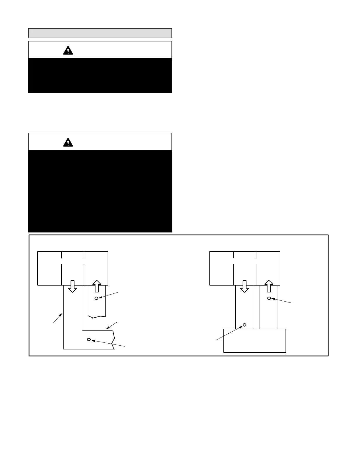
2- With all access panels in place, measure static
pressure external to unit (from supply to return).
Blower performance data is based on static pressure
readings taken in locations shown in figure 17.
Note - Static pressure readings can vary if not taken
where shown.
3- Measure the indoor blower wheel RPM.
4- Referring to the Blower Data tables, use static
pressure and RPM readings to determine unit
CFM. Use the Accessory Air Resistance tables
when installing units with any of the options or
accessories listed. Refer to table 3 for minimum
airflow when electric heat is installed.
FIGURE 17
LOCATION OF STATIC PRESSURE READINGS
SUPPLY AIR
READING
LOCATION
SUPPLY
RE
TURN
INSTALLATIONS WITH DUCTWORK
SUPPLY
RE
TURN
INSTALLATIONS WITH CEILING DIFFUSERS
MAIN
DUCT RUN
FIRST BRANCH
OFF OF MAIN RUN
DIFFUSER
ROOFTOP UNIT
ROOFTOP UNIT
SUPPLY AIR
READING
LOCATION
RETURN AIR
READING LOCATION
RETURN AIR
READING
LOCATION
 Loading...


