Page 20
LHT/LDT156, 180, 240
TABLE 6
180 Compressor 1 Frequency 56Hz - 581168-01
Outdoor
Coil En
tering
Air Temp
Circuit 1 Circuit 2
Dis. +10
psig
Suc. +5
psig
Dis. +10
psig
Suc. +5
psig
65°F 243 133 248 132
75°F 280 137 286 135
85°F 321 141 328 138
95°F 366 144 374 140
105°F 415 146 424 143
115 ° F 469 149 477 146
TABLE 7
240 Compressor 1 Frequency 68Hz - 581169-01
Outdoor
Coil En
tering Air
Temp
Circuit 1 Circuit 2
Dis +10
psig
Suc +5
psig
Dis. +10
psig
Suc +5
psig
65 °F 260 135 264 135
75 °F 297 136 304 136
85 °F 338 138 346 138
95 °F 384 140 394 140
105 °F 434 142 443 142
115 °F 485 144 494 144
E-Charge Verification - Approach Method - AHRI Testing
(Fin/Tube Coil)
1- Using the same thermometer, compare liquid
temperature to outdoor ambient temperature.
Approach Temperature = Liquid temperature (at
outdoor coil outlet) minus ambient temperature.
2- Approach temperature should match values in table
8. An approach temperature greater than value
shown indicates an undercharge. An approach
temperature less than value shown indicates an
overcharge.
3- The approach method is not valid for grossly over or
undercharged systems.
Use tables 6 through 7 as a
guide for typical operating pressures.
TABLE 8
APPROACH TEMPERATURES - FIN/TUBE COIL
Unit
Liquid Temp. Minus Ambient Temp.
1st Stage 2nd Stage
156
5°F + 1
(2.8°C +
0.5)
4.0°F + 1
(2.2°C +
0.5)
180
2°F + 1
(1.1°C +
0.5)
5.0°F + 1
(2.8°C +
0.5)
240
6°F + 1
(3.3°C +
0.5)
6°F + 1
(3.3°C +
0.5)
F-Compressor Controls
See unit wiring diagram to determine which controls are
used on each unit.
1- High Pressure Switch (S4, S7)
The compressor circuit is protected by a high
pressure switch which opens at 640 psig +
10 psig
(4413 kPa +
70 kPa) and automatically resets at 475
psig +
20 psig (3275kPa + 138 kPa).
2- Low Pressure Switch (S87, S88)
The compressor circuit is protected by a low
pressure switch. Switch opens at 40 psig +
5 psig
(276 +
34 kPa) and automatically resets at 90 psig
+
5 psig (621 kPa + 34 kPa).
3- Crankcase Heater (HR1, HR2)
Units have compressors which contain a belly band
compressor oil heater which must be on 24 hours before
running compressors. Energize by setting thermostat so
that there is no cooling demand, to prevent compressor
from cycling, and apply power to unit.
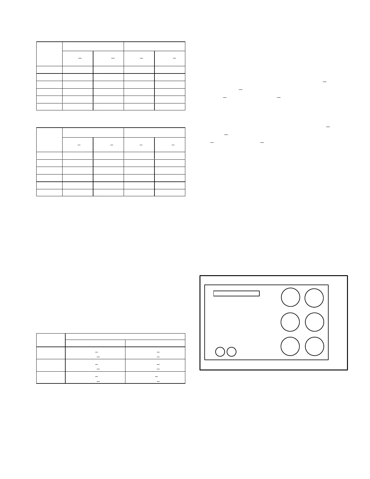
4- Outdoor Fan Operation
Outdoor fans 1, 2, and 3 are energized when
compressor 1 is energized. As cooling demand
increases, all six outdoor fans are energized. See
figure 16.
Outdoor fans 2, 3, 5, and 6 are de-energized when
outdoor temperature drops below 62°F (17°C).
OUTDOOR FANS
FIGURE 16
COND.
FAN 5
COND.
FAN 6
COND.
FAN 3
COND.
FAN 2
COND.
FAN 4
COND.
FAN 1
12
COMPRESSORS

 Loading...


