16
Table 3. Refrigerant Piping and Indoor Unit
Liquid Line
in.
Gas Line
in.
24000, 36000 &
48000
3/8 5/8
A
B
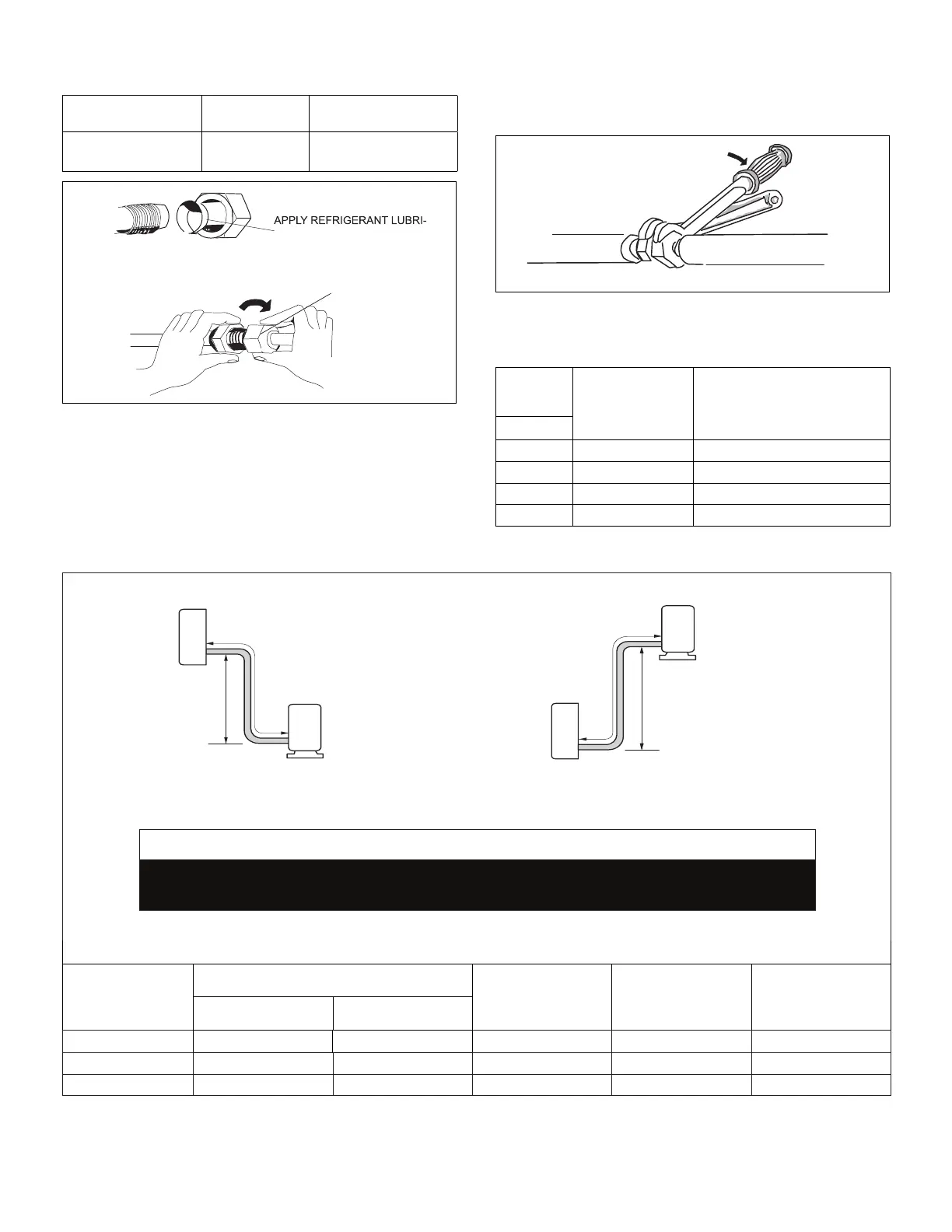
CANT ON THE OUTSIDE OF
THE FLARE
MALE FLARE
CONNECTION
Figure 31.
16. Once snug, continue another half-turn on each nut
which should create a leak-free joint. A torque wrench
may be used to tighten are nuts using “Table 4. Flare
Nut Torque Recommendations” on page 16. Do
17. After refrigerant piping has been installed and checked
for leaks, apply insulation over all ared connections.
TORQUE WRENCH
TO INDOOR
UNIT
TO OUTDOOR UNIT
BACKUP
WRENCH
Figure 32. Tighten Flare Nut
Table 4.
Outside
Diameter
Torque
Finger tighten and use an
appropriately sized wrench to
turn an additional:
1/4 15 ft.-lb. (20 N) 1/4 turn
3/8 26 ft.-lb. (35 N) 1/2 turn
1/2 41 ft.-lb. (56 N) 7/8 turn
5/8 48 ft.-lb. (65 N) 1 full turn
Table 5. Refrigerant Line Set Requirements
OUTDOOR UNIT
OUTDOOR UNIT
INDOOR UNIT
INDOOR UNIT
Maximum Line Set
Length
Maximum Line Set
Length
Maximum
Elevation -
Outdooor
Unit BELOW
Indoor Unit
Maximum
Elevation -
Outdooor
Unit ABOVE
Indoor Unit
Minimum Line Set
Length - 10 ft. (3m)
Minimum Line Set
Length - 10 ft. (3m)
Outside Unit BELOW Indoor Unit Outside Unit ABOVE Indoor Unit
Do not allow for excess length of line sets to be left rolled up as part of the
required distance, or in general. This will also cause additional performance issues.
IMPORTANT
Each system size has a line set length and vertical elevation parameters.
Maximum Elevation
Outdoor Unit BELOW
Indoor Unit - Feet
Maximum Elevation
Outdoor Unit ABOVE
Indoor Unit - Feet
Maximum Line
Set Length - Feet
Liquid Gas
018
1/4 1/2
66 ft. (20 m) 66 ft. (20 m) 98 ft. (30 m)
024 3/8 5/8 82 ft. (25 m) 82 ft. (25 m) 164 ft. (50 m)
036/048 3/8 5/8 98 ft. (30 m) 98 ft. (30 m) 213 ft. (65 m)
 Loading...