11
Ceiling Installation
• Locate a suitable position within the space where
maintenance access and supply air will not be restrict-
ed or affected by obstacles
• Suspend the unit from a ceiling which is capable of
supporting the unit’s weight
Units are suspended from the ceiling using
installed hanging brackets.
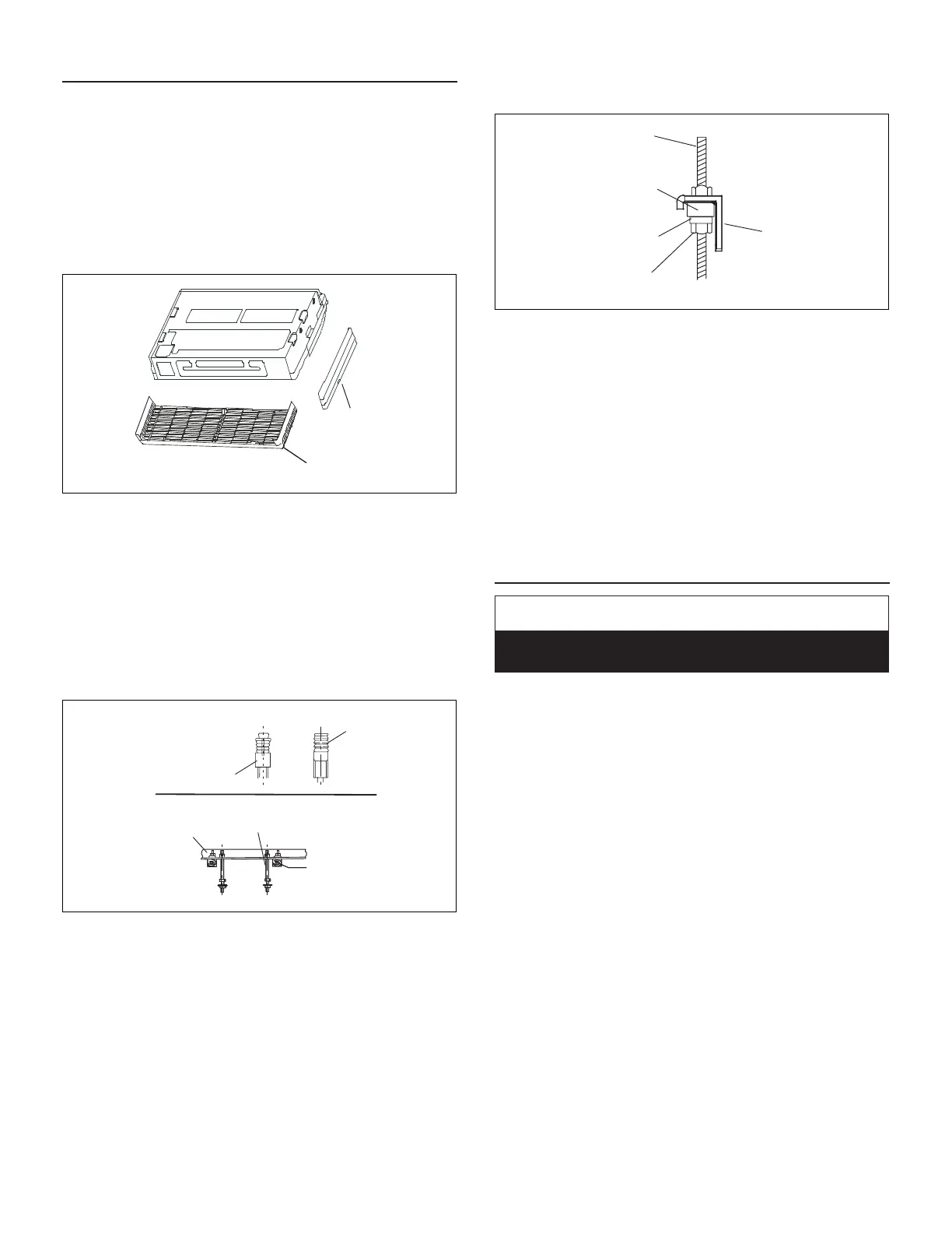
1. Remove the side panels and grille to expose factory-
installed hanging brackets on the sides of the unit
Figure 14. Remove Side Panel and Grille
2. Install suspension rods in the structural
ceiling or concrete slab in a suitable location.
If the structural ceiling is constructed of concrete,
install anchors to accept four suitably sized threaded
rods to suspend the indoor unit. If the structural ceiling
includes wooden joists, use angle iron or Unistrut
channel xed securely in place to accept the threaded
rods.
3. Slide one nut and one washer onto each threaded rod.
Rod
Anchor
Wooden
Joist
Threaded
Rod
Angle Iron Bolted
in Place Across
Wooden Joists
CONCRETE CEILING
USING ANCHORS
ANGLE IRON
ACROSS WOODEN
JOISTS
Figure 15.
4. Use electrical tape to keep the washer from falling off.
Position the nuts
5. Slide a second washer and then a second nut onto
each rod slightly above the nal resting place of the
hanging brackets.
6. If necessary, install a eld-provided isolation grommet
to prevent transmission of vibration from unit to
structural ceiling.
hreaded Rod
Suspension
Bracket
Leveling
Washer
Field-Provided
Isolation
Grommet
Figure 16.
7. Use either a mechanical lifting device or a minimum of
two people to raise the unit.
8. Hang the unit by sliding the factory-installed hanging
brackets on to the threaded rods between the sets of
washers and nuts.
9. Use the leveling nut (beneath hanging brackets)
to adjust the unit to the correct height. Remove the
electrical tape holding the upper washers and nuts
in place and tighten each of the four nuts above the
brackets down onto the brackets. This will ensure that
the unit remains level.
Indoor Unit Condensate Piping Connections
IMPORTANT
Make sure that drain piping is properly routed and
insulated to prevent both leaks and condensation.
1. Use a eld-provided hose clamp to secure the drain
line stub on the side of the cassette base to a eld-
supplied 1” (25 mm) drain line.
NOTE: Take care not to over-tighten the hose clamp as
this may damage the drain line stub.
NOTE: Connection between stub and drain line must be
watertight. Apply non hardening plumbing joint
compound if needed to ensure a watertight seal.
2. Conrm proper slope (not less than 1/4 inch per foot
(18 mm per m)) and routing of condensate lines to
ensure moisture is drained away from the indoor unit.
3. Drain should be as short as possible and should
not have any droops or kinks that would restrict
condensate ow and shall be approved resistant pipe.
ensure that the line will drain freely.
 Loading...