Page 19
Leak Check
-
stalled piping connections for gas leaks. Use a commer-
-
test for gas leaks.
NOTE - If emergency shuto is necessary, shut o the
main manual gas valve and disconnect the main power
to the furnace. The installer should properly label these
devices.
CAUTION
Some soaps used for leak detection are corrosive to
certain metals. Carefully rinse piping thoroughly after
leak test has been completed. Do not use matches,
gas leaks.
The furnace must be isolated from the gas supply sys-
tem by closing the individual manual shut-o valve during
any gas supply system at pressures greater than or equal
to ½ psig. (3.48 kPa, 14 inches w.c.). This furnace and
its components are designed, manufactured and inde-
pendently certied to comply with all applicable ANSI/CSA
standards. A leak check of the furnace and its components
is not required.
IMPORTANT
When testing pressure of gas lines, gas valve must be
can be damaged if subjected to pressures greater than
1/2 psig (3.48 kPa, 14 inches w.c.).
.
MANUAL MAIN
SHUT-OFF VALVE
WILL NOT HOLD
NORMAL TEST
PRESSURE
CAP
ISOLATE
GAS VALVE
FURNACE
1/8 NPT PLUG
Figure 19
Electrical
ELECTROSTATIC DISCHARGE (ESD)
Precautions and Procedures
CAUTION
components. Take precautions to neutralize
electrostatic charge by touching your hand
and tools to metal prior to handling the
control.
WARNING
Fire Hazard. Use of aluminum wire with this product may
or death. Use copper wire only with this product.
CAUTION
Failure to use properly sized wiring and circuit breaker
may result in property damage. Size wiring and circuit
unit rating plate.
hand side of the cabinet. The make-up box may be moved
-
lation. If the make-up box is moved to the right hand side,
clip the wire ties that bundle the wires together. Secure
the excess wire to the existing harness to protect it from
damage.
The power supply wiring must meet Class I restrictions.
Protected by either a fuse or circuit breaker, select circuit
protection and wire size according to unit nameplate.
NOTE - Unit nameplate states maximum current draw.
Maximum over-current protection allowed is 15 AMP.
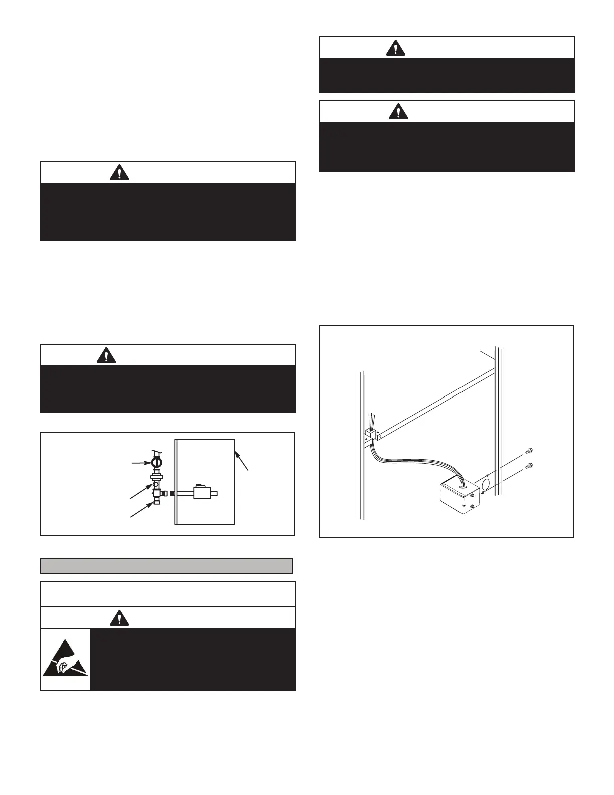
INTERIOR MAKE-UP BOX INSTALLATION
(Right Side)
MAKE-UP
BOX
Cut the two wire ties to extend power wires for right side onl
Figure 20
-
Holes are on both sides of the furnace cabinet to facilitate
wiring.
Install a separate (properly sized) disconnect switch near
Before connecting the thermostat, check to make sure
the wires will be long enough for servicing at a later date.
Make sure that thermostat wire is long enough to facilitate
future re oval of blower for service.
Complete the wiring connections to the equipment. Use
-
is suitable for Class II rating for thermostat connections.