Page 27
Blower Delay Select
SW2-1 SW2-2
60 OFF ON
90 OFF OFF
120 ON OFF
180 ON ON
Factory Setting is 90
HEAT FAN‐OFF TIME IN SECONDS
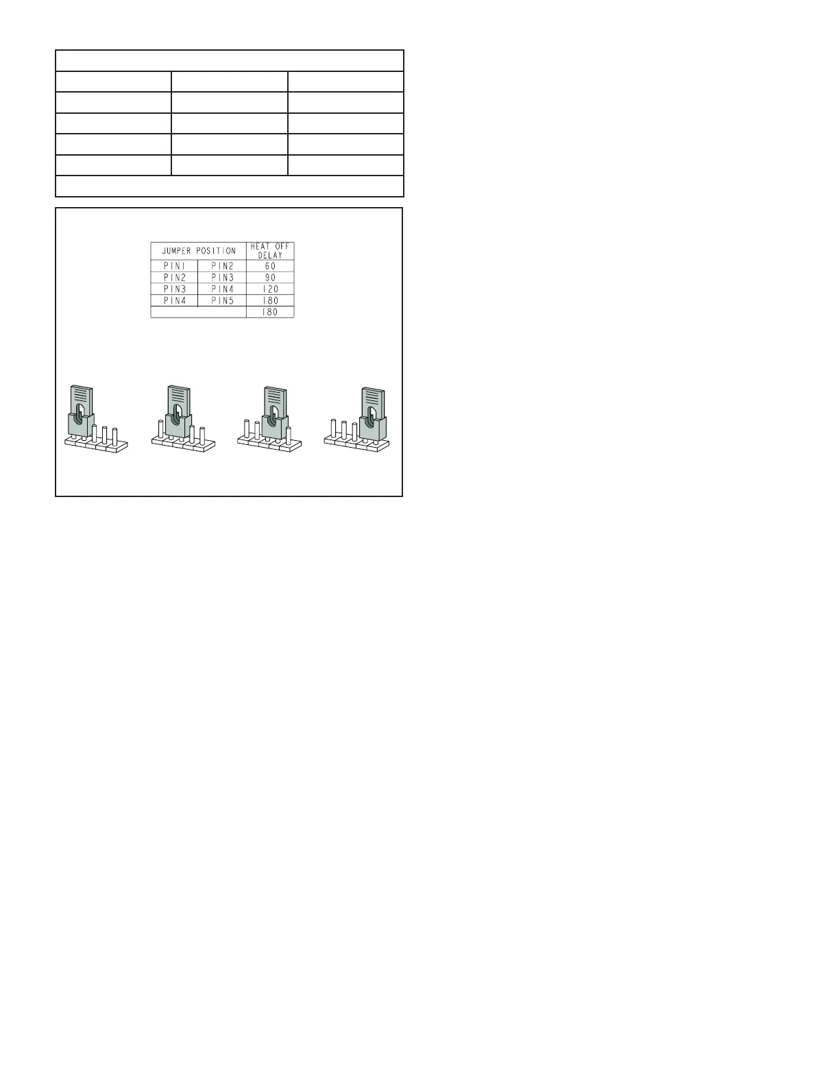
To adjust fan-off timing, reposition jumper across pins to
achieve desired setting.
NO JUMPER
60
90
120
180
60
90
120
180
60
90
120
180
60
90
120
180
60 Second
off Time
90 Second
off Time
120 Second
off Time
180 Second
off Time
Figure 24
Constant Torque Motor
ML180DFE units are equipped with a permanent magnet-
ic indoor blower motor that provides constant torque. The
-
nal common. Each tap requires 24 volts to be energize.
Flame Rollout Switches
These manually reset switches are located on the burner
box.
Input Voltage Requirements
The circuit is designed to be operated with AC voltage. A
voltage of 12 to 33VAC is required to energize the motor.
Expected current draw will be less than 20mA.
Electrical
1 - Check all wiring for loose connections.
2 - Check for the correct voltage at the furnace operating).
Correct voltage is 120VAC + 10%
3 - Check amp-draw on the blower motor with blower
access panel in place.
Motor Nameplate__________Actual__________
Blower Speeds
Follow the steps below to change the blower speeds.
1 -
2 - Remove blower access panel.
3 - Disconnect existing speed tap at integrated control
speed terminal.
NOTE - Termination of any unused motor leads
must be insulated.
4 - Place unused blower speed tap on integrated control
“PARK” terminal or insulate.
5 - Refer to blower speed selection chart on unit wiring
diagram for desired heating or cooling speed. See
Blower performance data beginning on the next
page.
6 - Connect selected speed tap at integrated control
speed terminal.
7 - Resecure blower access panel.
8 - Turn on electrical power to furnace.
9 - Recheck temperature rise.
Electronic Ignition
The integrated control has an added feature of an internal
Watchguard control. The feature serves as an automat-
ic reset device for integrated control lockout caused by
ignition failure. This type of lockout is usually due to low
gas line pressure. After one hour of continuous thermostat
demand for heat, the Watchguard will break and remake
thermostat demand to the furnace and automatically reset
the integrated control to begin the ignition sequence.