Page 49
Winterizing and Condensate Trap Care
1 - Turn off power to the furnace.
2 - Have a shallow pan ready to empty condensate water.
3 - Remove the clean out cap from the condensate trap
and empty water. Inspect the trap then reinstall the
clean out cap.
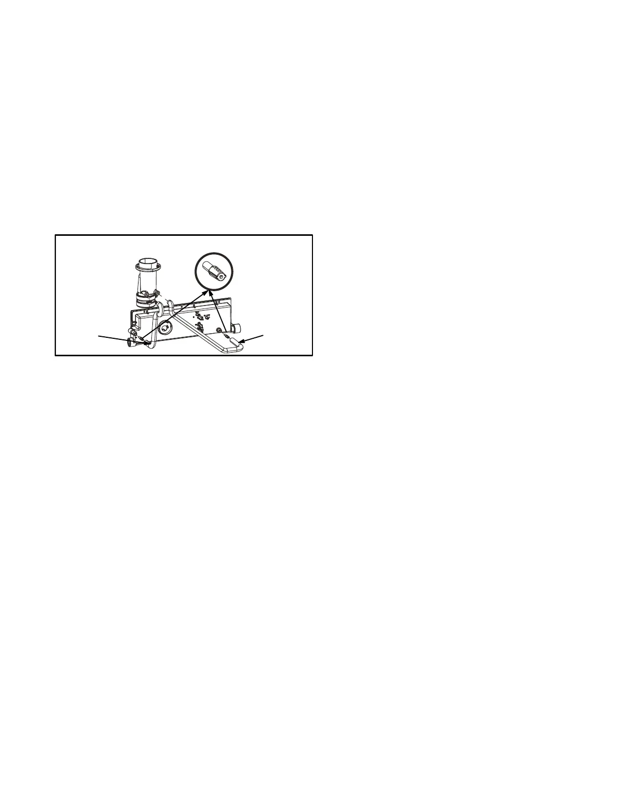
Condensate Hose Screens (Figure 62)
Check the condensate hose screens for blockage and
clean if necessary.
1 - Turn off power to the unit.
2 - Remove hoses from cold end header box. Twist and
pull screens to remove.
3 - Inspect screens and rinse with tap water if needed.
4 - Reinstall screens, reconnect hoses and turn on power
to unit.
FIGURE 62
Condensate Hose Screens
Hose
Hose
Cleaning Heat Exchanger
If cleaning the heat exchanger becomes necessary, follow
the below procedures and refer to figure 1 when disassem
bling unit. Use papers or protective covering in front of fur
nace while removing heat exchanger assembly.
1 - Turn off electrical and gas supplies to the furnace.
2 - Remove the furnace access panels.
3 - Disconnect the 2 wires from the gas valve.
4 - Remove gas supply line connected to gas valve. Re
move the burner box cover (if equipped) and remove
gas valve/manifold assembly.
5 - Remove sensor wire from sensor. Disconnect 2‐pin
plug from the ignitor.
6 - Disconnect wires from flame roll-out switches.
7 - Disconnect combustion air intake pipe. It may be nec
essary to cut the existing pipe to remove burner box
assembly.
8 - Remove four burner box screws at the vestibule panel
and remove burner box. Set burner box assembly
aside.
NOTE - If necessary, clean burners at this time. Follow
procedures outlined in Burner Cleaning section.
9 - Loosen the clamps to the flexible exhaust coupling.
10 - Disconnect condensate drain line from the cold end
header box.
11 - Disconnect condensate drain tubing from flue collar.
Remove screws that secures the flue collar into place.
Remove flue collar. It may be necessary to cut the exit
ing exhaust pipe for removal of the fitting.
12 - Mark and disconnect all combustion air pressure tub
ing from cold end header collector box.
13 - Mark and remove wires from pressure switch assem
bly. Remove the assembly. Keep tubing attached to
pressure switches.
14 - Disconnect the plug from the combustion air inducer.
Remove two screws which secure combustion air in
ducer to collector box. Remove combustion air induc
er assembly. Remove ground wire from vest panel.
15 - Disconnect the condensate drain line.
16 - Remove cold end header box.
17 - Remove electrical junction box from the side of the fur
nace.
18 - Mark and disconnect any remaining wiring to heating
compartment components. Disengage strain relief
bushing and pull wiring and bushing through the hole in
the blower deck.
19 - Remove the primary limit from the vestibule panel.
20 - Remove two screws from the front cabinet flange at
the blower deck. Spread cabinet sides slightly to allow
clearance for removal of heat exchanger.
21 - Remove screws along vestibule sides and bottom
which secure vestibule panel and heat exchanger as
sembly to cabinet. Remove two screws from blower
rail which secure bottom heat exchanger flange. Re
move heat exchanger from furnace cabinet.
22 - Back wash heat exchanger with soapy water solution
or steam. If steam is used it must be below 275°F
(135°C) .
23 - Thoroughly rinse and drain the heat exchanger. Soap
solutions can be corrosive. Take care to rinse entire
assembly.
24 - Reinstall heat exchanger into cabinet making sure that
the clamshells of the heat exchanger assembly is en
gaged properly into the support bracket on the blower
deck. Remove the indoor blower to view this area
through the blower opening.
25 - Re‐secure the supporting screws along the vestibule
sides and bottom to the cabinet.
26 - Reinstall cabinet screws on front flange at blower
deck.
27 - Reinstall the primary limit on the vestibule panel.
28 - Route heating component wiring through hole in blow
er deck and reinsert strain relief bushing.
29 - Reinstall electrical junction box.
30 - Reinstall the cold end header box.
31 - Reinstall the combustion air inducer. Reconnect the
plug to the wire harness.
32 - Reinstall pressure switches and reconnect pressure
switch wiring.
33 - Carefully connect combustion air pressure switch
tubing from pressure switches to proper ports on
cold end header collector box.
34 - Reconnect condensate drain line to the cold end
header box.
 Loading...