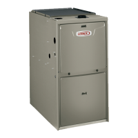
1
2
3
4
5
6
7
8
9
10
11
12
1/16
TURN
Page 20
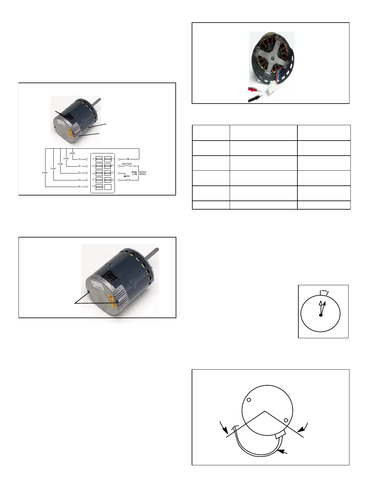
Replacing the Motor Module
1. Disconnect electrical power to unit.
2. Remove unit access panel.
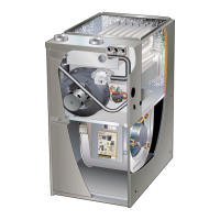
3. Unplug the two harnesses from the motor control mod
ule. See figure 17.
TWO HARNESS
CONNECTIONS
MOTOR CONTROL MODULE
MOTOR
FIGURE 17
Unplug the Two Harness Connection
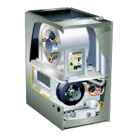
4. Remove the two hex head bolts securing the motor
control module to the motor (see figure 18).
REMOVE BOTH HEX
HEAD BOLTS
FIGURE 18
Remove the Hex Head Bolts
5. Slide the motor control module away from the motor to
access and disconnect the internal three wire connec
tor. It is not necessary to remove blower motor itself.
Set both hex head bolts aside.
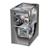
Testing the Motor (Figure19)
If any motor fails the below tests, do not install the new con
trol module. The motor is defective and it also must be re
placed. The new control can fail if placed on a defective mo
tor.
1. Using an ohmmeter check the resistance from any one
of the motor connector pins to the aluminum end plate
of the motor. This resistance should be greater than
100k ohms.
2. Check the resistances between each of the three mo
tor connector pins. These should all read approxim
ately the same resistance within an ohm.
3. Check to see if the blower wheel spins freely.
FIGURE 19
Motor Test
TABLE 8
Scale
Measurement range in
words
ohms
2 M
two megohm-two million
ohms
0 - 2,000,000
200 K
two hundred kilo-ohm-two
hundred thousand ohms
0 - 200,000
20 K
twenty kilo-ohm-twenty
thousand ohms
0 - 20,000
2 K
two kilo-ohm two-thousand
ohms
0 - 2,000
200 two hundred ohms 0 - 200
Motor Module Installation
All replacement motor control modules look similar; how
ever, each module is designed for a specific motor size. It is
very important to make sure that you are using the correct
replacement motor control module. USE OF THE WRONG
MOTOR CONTROL MODULE MAY RESULT IN UNEX
PECTED UNIT OPERATION.
1. Verify electrical power to unit is disconnected.
2. Connect three-wire harness from motor to control
module.
3. Mount new motor control module
to motor using two hex head bolts
removed in figure 18. Torque bolts
to 22 inch pounds or 1/16
th
clock
turn as exampled to the right.
4. Reconnect the two harnesses to
the motor control module.
5. The electrical connectors of the motor should be facing
down to form a drip loop (figure20). This will directs
moisture away from the motor and its electric connec
tions on the motor.
CONNECTOR
ORIENTATION
BETWEEN 4 AND 8
O'CLOCK
BACK OF CONTROL
MODULE
DRIP LOOP
FIGURE 20
Drip Loop
 Loading...