Page 20
Pressure Switch Check
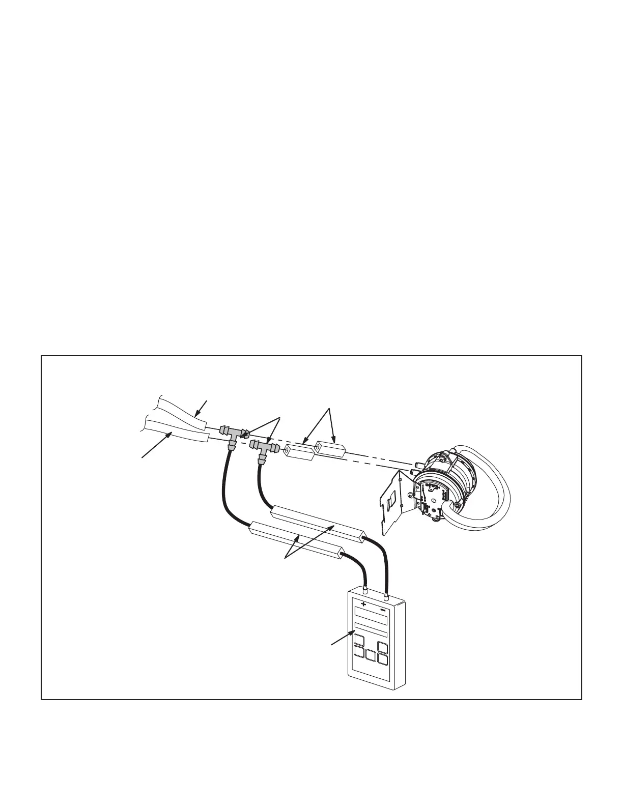
To check pressure switch dierential, refer to FIGURE 15
and use the provided ttings and tubing to follow the steps
below.
1 - Remove thermostat demand and allow unit to cycle
o.
2 - Remove the tubing from the negative side (red
and black or red) and positive side (black) of the
pressure switch (leave both connected to cold end
header box).
3 - Take the 2” length square tubing and connect to the
positive (+) side of the pressure switch. Take the 10”
length square tubing and tee into the tubing from
the positive side of the cold end header box and
the other side of the 2” square tubing. Connect the
other end of the 10” square tubing the the positive
(+) side of the measuring device.
4 - Take a second piece the 2” length square tubing
and connect to the negative (-) side of the pressure
switch. Take a second piece of 10” length square
tubing and tee into the tubing from the negative (-)
side of the cold end header box and the other side
of the 2” square tubing. Connect the other end of
the 10” square tubing the the negative (-) side of the
measuring device.
5 - Operate unit and observe manometer reading.
Readings will change as heat exchanger warms.
a. Take one reading immediately after start-up.
b. Take a second reading after unit has reached steady
state (approximately 5 minutes). This will be the pressure
dierential.
The pressure dierential should be at least 0.15”
greater than those listed in the table 8. Readings in
table are the set points or “break points”.
6 - Remove thermostat demand and allow to cycle o.
7 - Replace original pressure switch tubing.
NOTE - Pressure dierential values (set point)
in table are the ”break”, or ”open” specications.
”Make”, or ”close” pressure dierentials are 0.15”
greater than the set points listed in table.
PRESSURE SWITCH CHECK
Black Tubing
(positive +)
Red and Black
or Red Tubing
(negative −)
Tee
2” long Square
Tubing
Measuring Device
10” Long Square Tubing
FIGURE 15
 Loading...