M
mitchellrichardAug 4, 2025
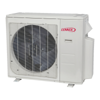
What to do if my Lennox MLA009S4S-1P shows an outdoor EEPROM malfunction?
- DDean LewisAug 4, 2025
If your Lennox Air Conditioner displays an outdoor EEPROM malfunction, try these steps: * Power off the unit, then restart it after 3 minutes. * If the issue persists, the outdoor main PCB may need to be replaced.