• 20 •
01 07
02 08
03 09
04 10
05 11
06 12
08
01
02
04
05
07
09
10
11
12
03
03
06
08
0101
0202
0404
06
05
0707
09
10
1111
1212
0303
0303
NAC/NAH
200 - 230 - 270 - 300
NAC 340 - 380 - 420 - 480 - 540 - 600 - 640
NAH 340 - 380 - 420 - 480
V
Q
Dt
Application Guide / NEOSYS-AGU-1801-E
HYDRAULIC DATA
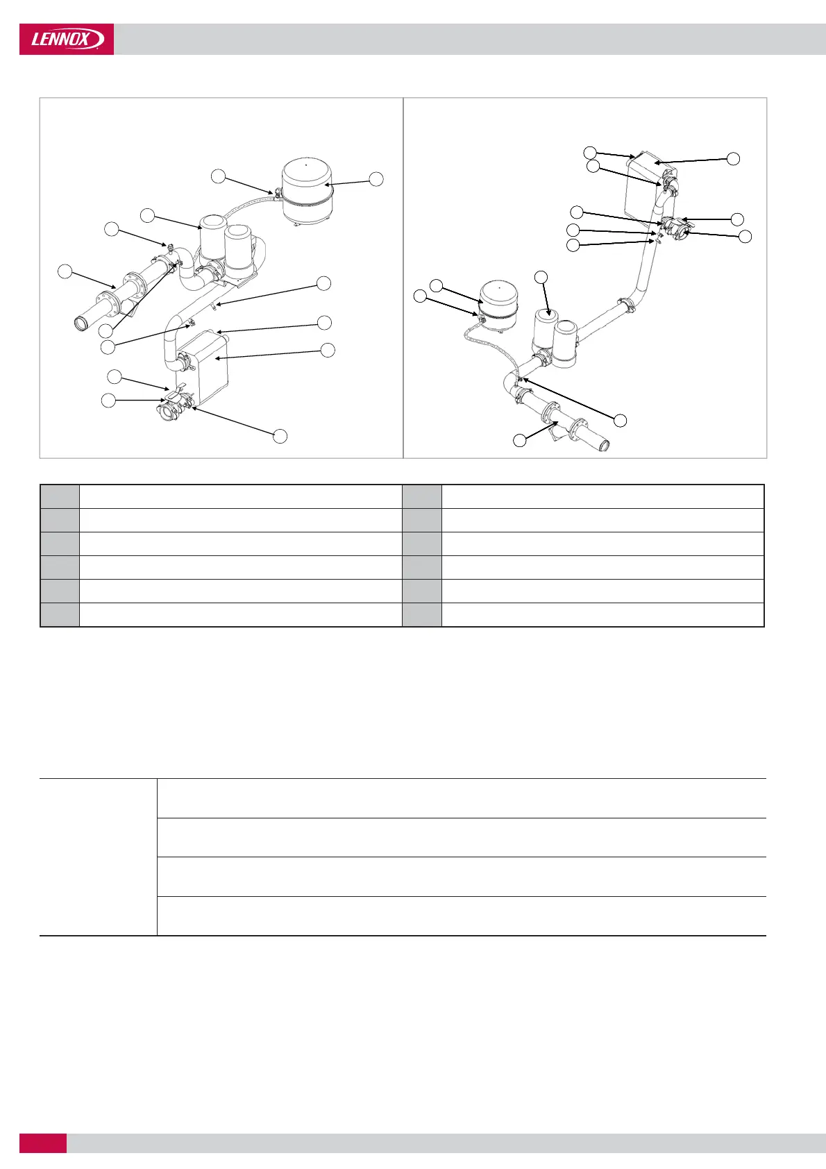
UNIT WITH HYDRAULIC MODULE
Water fi lter (item supplied loose) Electronic fl ow switch
Air purge Plate heat exchanger
Pressure tap Setting valve
Pump Pressure tap and drain valve
Safety valve with manometer Return temperature sensor
Expansion vessel Supply temperature sensor
IN
OUT
Vmini = 86 x Q / (Nstages x Dt)
Where :
Minimum water content of the installation
Cooling capacityof the chiller
Nstage Number of control steps available in the unit
Maximum acceptable temperature rise (Dt = 6°c for an air conditioning application)
Important note: In case NEOSYS is used in air-conditioning applications with a short water system (e.g. NEOSYS application with air
handling units) or in case NEOSYS is used for industrial process cooling, it is mandatory to use a buffer tank.
MINIMUM WATER CONTENT OF AN INSTALLATION
Thanks to multi step capacity control and smart anti-short compressor cycling, NEOSYS can work with minimum water loop volume
as defi ned here below. This can eliminate the need for a buffer tank in most of air-conditioning applications (e.g. NEOSYS application
with fan-coil units).
 Loading...