• 21 •
NAC
200
4 717
230
4 824
270
4 968
300
4 1075
340
5 975
380
5 1089
420
6 1003
480
6 1147
540
6 1290
600
6 1433
640
6 1529
680
10 975
760
10 1089
840
12 1003
960
12 1147
1080
12 1290
5 m 10 m 5 m 10 m
200-230-270
300-340-380
420-480
540
600-640
50 l 1,5 Bar 5 230 l 4 180 l 4 020 l 3 210 l
NAH
200
4 717
230
4 824
270
4 968
300
4 1075
340
5 975
380
6 908
420
6 1003
480
6 1147
+ 5°C ► 0°C 10% 1,05 1,02 0,99 0,994
0°C ► -5°C 20% 1,10 1,05 0,98 0,993
- 5°C ► -10°C 30% 1,15 1,08 0,97 0,99
- 10°C ► -15°C 35% 1,18 1,10 0,96 0,987
Application Guide /NEOSYS-AGU-1801-E
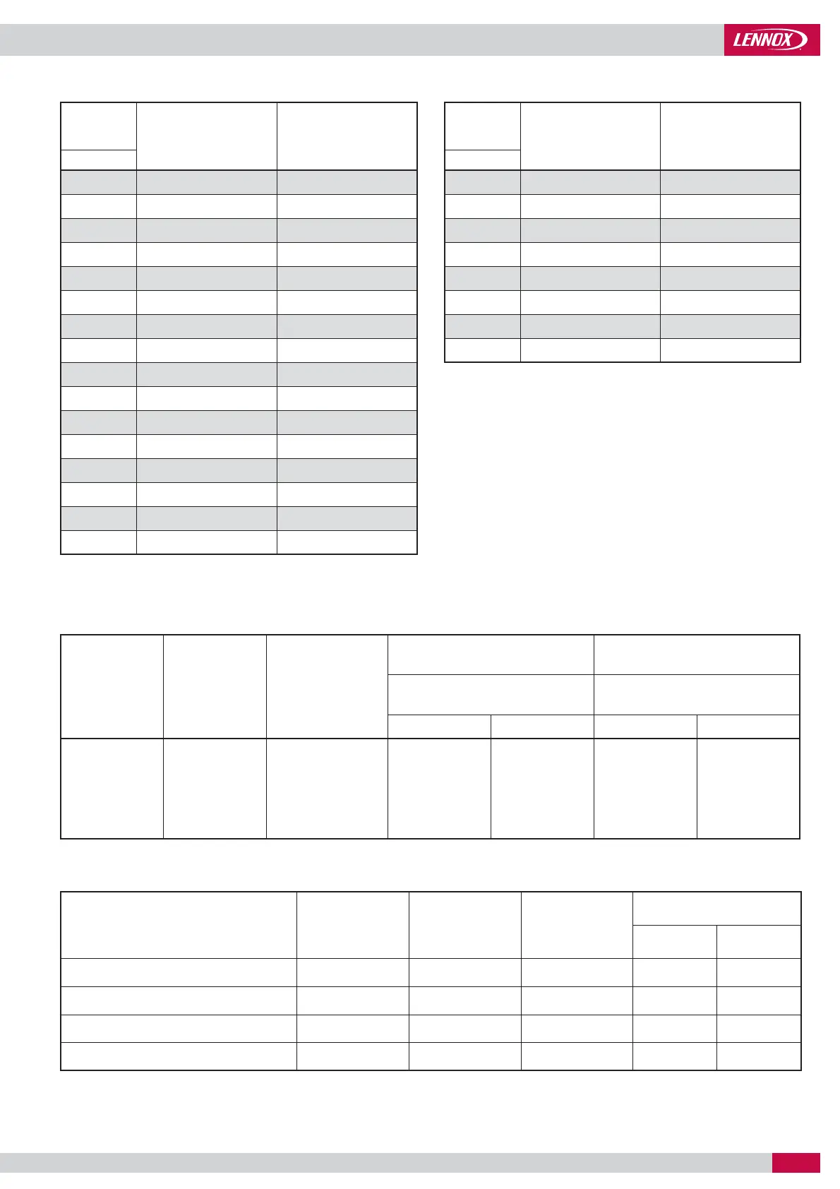
Unit Size
Number of stages
Mini water volume
(l)
MAXIMUM WATER CONTENT OF AN INSTALLATION
The maximum water content of the installation is determined by the capacity of the expansion vessel.
On units fi tted with a standard Hydraulic Module it is possible to determine the maximum water content of the installation.
Unit Size
Expansion
vessel
volume
Pressure in
the expansion
vessel
Max. volume clear water (l) Max. volume Glycol water (l)
Static pressure Static pressure
HYDRAULIC DATA
MINIMUM WATER CONTENT OF AN INSTALLATION
Unit Size
Number of stages
Mini water volume
(l)
GLYCOL CORRECTION FACTOR
Example : 10% glycol
Minimum fl ow : 1,19 m
3
/h x 1,02
Pressure drop x 1,07
System capacity x 0,99
Minimum ambient temperature or water
outlet temperature
Ethylene
glycol
Pressure
drop
Water
fl ow
CAPACITIES
Cooling Heating
 Loading...