• 22 •
200
208 21,5 35,8 57,9
230
236 24,4 40,6 57,9
270
273 28,1 46,9 57,9
300
308 31,7 52,9 126,4
340
351 36,2 60,4 126,4
380
387 40,0 66,6 126,4
420
430 44,3 73,9 126,4
480
490 50,6 84,3 126,4
540
531 54,8 91,3 126,4
600
605 62,5 104,1 126,4
640
627 64,7 107,9 126,4
680
702 72,6 121,0 252,9
760
774 80,1 133,4 252,9
840
860 88,8 148,0 252,9
960
980 101,3 168,8 252,9
1080
1062 109,7 182,9 252,9
Application Guide / NEOSYS-AGU-1801-E
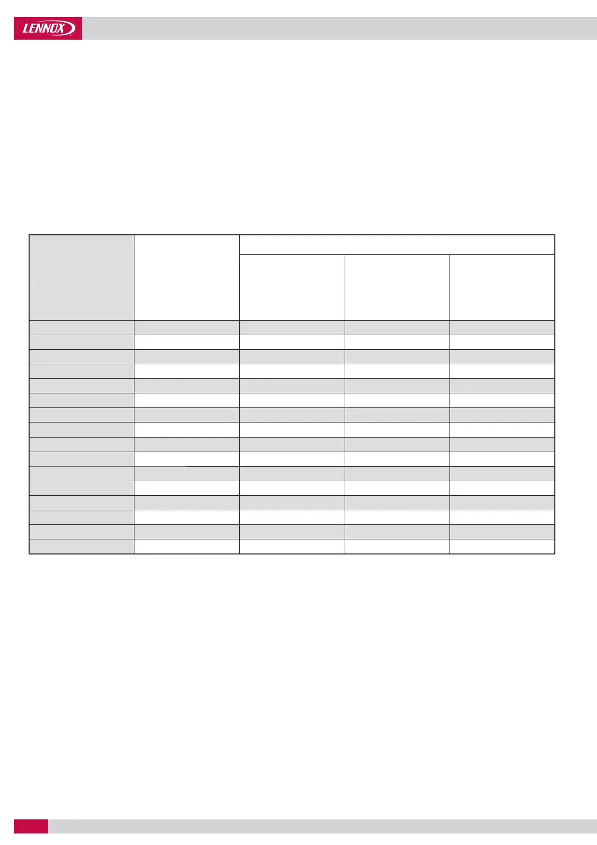
HYDRAULIC DATA
MINIMUM WATER FLOW THROUGH THE EVAPORATOR
In case of installation with fi xed speed pump, to prevent from freezing risk, the fl ow rate through the evaporator must be higher than
the minimum fl ow given in the table below.
In case of variable primary fl ow, the pump speed must be controlled through the CLIMATIC control. Additionally, the hydraulic system
must be properly designed and balanced to ensure a right water fl ow distribution through the chiller evaporator and the terminal units.
This is especially important when the system is designed with fan coils equipped with two-way valves. When the two-way valves are
closing in response to building load change, it is important that the system is designed to ensure a minimum evaporator fl ow that is
always minimum 60% of the chiller’s design fl ow rate. This can be done with a bypass from chilled water supply to chilled water return
opened via a signal from a fl ow meter.
Additionnaly, some terminals can be fi tted with three way control valves in order to ensure the fl ow will not drop below the minimum
value at any load condition as indicated in the table below.
Models Capacity (kW)
Water fl ow rate (m³/h)
Minimum
(with fi xed and eDrive™
variable speed pump)
Nominal Maximum
Important note : The water fl ow must not vary by more than 10% per minute. If the fl ow rate changes more rapidly, the system should
contain a minimum of 6,5 litres of water per kW instead of 3 l/kW.
 Loading...