Page 3
M2 unit controller LED indicators
Some indicators on the circuit board are visible with the cover in place; others are not. The indicators and their meanings are
described in table 1.
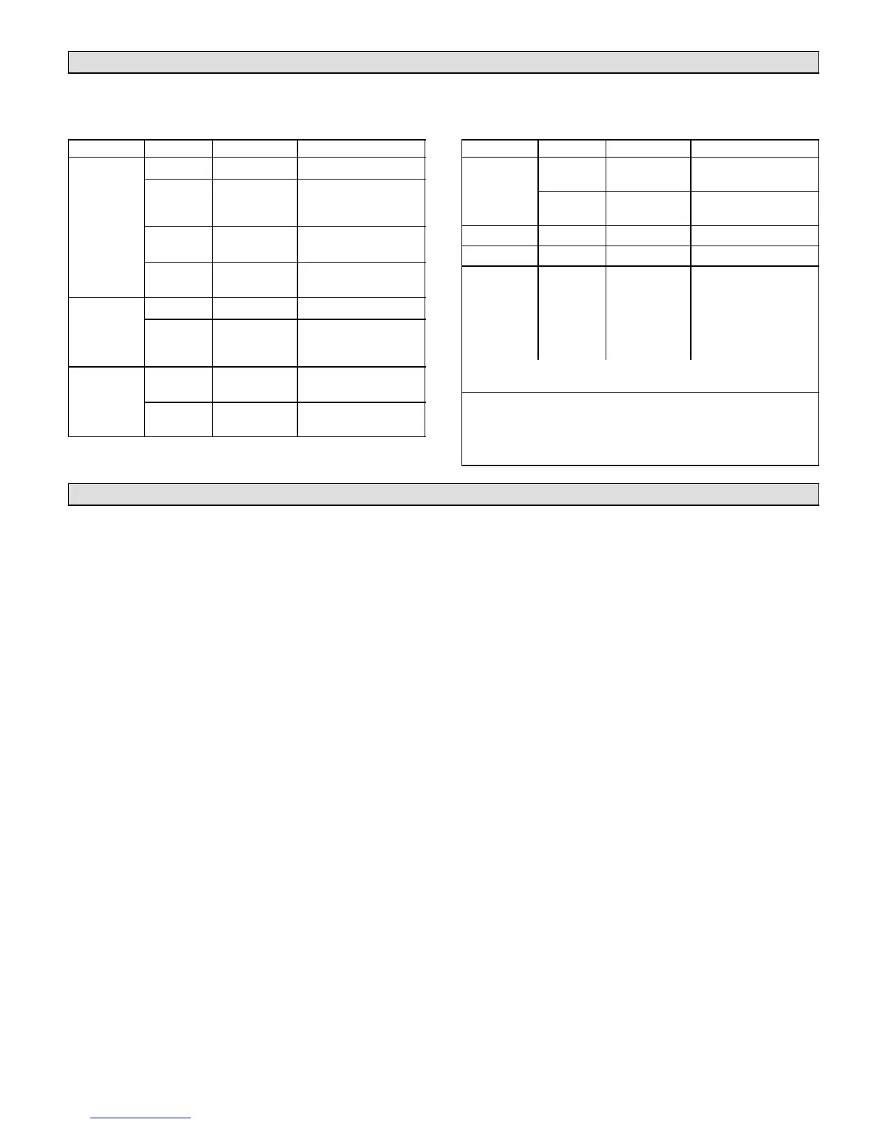
Table 1. LED operation indications
LED Status Indication Meaning
Heartbeat green Slow Flash Normal Operation
green Fast Flash Check 24V, update
firmware, or replace
board
green Steady Off No voltage to M2 board
or defective board
green Steady On Defective Board (re-
place)
OAS
green Steady ON Outside air is suitable
green Flashing
IAQ mode or mechani-
cal cooling during free
cooling
PC
Connection
Local
(amber)
Flickering ON
Communication to PC
USB connector
Network
(green)
Flickering ON
Network communica-
tion
LED Status Indication Meaning
S−BUS BUS
(green)
Flickering ON Network traffic present
TX
(amber)
Flickering ON M2 is transmitting
BACnet RX (green) Flickering ON M2 is receiving
TX (red) Flickering ON M2 is transmitting
Thermostat
Input
amber Indicates a
thermostat de-
mand
G− Blower on
W1− 1st stage heat
W2− 2nd stage heat
Y1− 1st stage cool
Y2− 2nd stage cool
OCP−Occupied
Thermostat LEDs indicate only with incoming thermostat connection
vis SmartWire connector.
Slow Flash = 1 sec on; 1 sec off.
Fast Flash = 1 msec on; 1 msec off.
A flickering" LED flashes significantly faster than a fast flash.
NOTE − LEDs are energized by 24 vac thermostat inputs.
Startup
Connections between RTU & M2 unit controller
The M2 unit controller connects to the rooftop unit using
SmartWiret connectors. Each connector is keyed" so
that no connector can be installed in the wrong location. Be
sure all connectors are in place and completely inserted
(see figure 1).
Sensor Common Isolation
Thermostat (TSTAT) and humidity (HUM) sensor com-
mons may be isolated if they are powered remotely. Slide
switch to OPEN to isolate (see figure 1).
USB interface usage
The USB port is used for service verification and for down-
loading reports. Onsite data collection requires use of a
USB flash drive. Data written to the drive includes date,
time, serial number, catalog number, basic data, and error
code buffer. Technicians then transfer the data to a PC and
then forward encrypted files to billing personnel for service
history verification.
PC interface
The PC interface is used with unit controller software to
change programming. The M2 interface uses a USB A to B
male cable. You may also continue to use 9 pin/RS485
connection to the phone jack or S−BUS connector as be-
fore. A list of service connection kits is on Page 20.
SmartWire Field Wiring Connections
The SmartWire connectors, P297, P298 and P299, al-
low for easy field wiring connection points.
2−amp fuseThe 24VAC supply outputs, (R), on these
connectors are routed through the fuse, F1. This fuse is a
standard 2−amp, automotive−style blade fuse. This fuse
protects the Prodigy controller from field wiring mis−wires.
TSTAT COMThe switch "TSTAT COM" is located to the
left of P297. This switch is used only in unique situations
where the device supplying the thermostat signals to the
Prodigyt controller has its own power source and does
not share a common reference voltage with the Prodigyt
controller. Otherwise the TSTAT COM switch needs to be
set to the default, closed position, to the right.
HMD COMThe switch "HMD COM" is located to the right
of P299. This switch is used only in unique situations
where the device supplying the dehumidify command sig-
nal to the Prodigyt controller has its own power source
and does not share a common reference voltage with the
Prodigyt controller. Otherwise the HMD COM switch
needs to be set default, closed position, to the left.

 Loading...


