EasyManua.ls Logo

Lennox M0STAT61Q-1 - User Manual

Lennox M0STAT61Q-1
12 pages
Print Icon
To Next Page IconTo Next Page
Loading...
©2018 Lennox Industries Inc.
Dallas, Texas, USA
INSTALLATION/
OPERATION
INSTRUCTIONS
CONTROLS
507561-04
8/2018
Supersedes 507561-03
This manual must be left with the
owner for future reference.
Shipping and Packing List
Package 1 of 1 contains;
1 – Wired Controller
1 – Installation and operation manual
1 – Cable with connector – 20 ft. (6 m)
IMPORTANT!
Frequent changes to operating mode
may cause system malfunction.
Allow at least one minute between
mode changes to allow the system to
stabilize.
Lennox Mini-Split
Systems Wired Indoor Unit
Controller (M0STAT61Q-1)
WARNING
Improper installation, adjustment,
alteration, service or maintenance
can cause property damage, personal
injury or loss of life.
Installation and service must be
performed by a licensed professional
HVAC installer (or equivalent) or
service agency.
Question and Answer IconNeed help?

Do you have a question about the Lennox M0STAT61Q-1 and is the answer not in the manual?

Summary

Controller Overview

Shipping and Packing List

Lists contents of the package, including the wired controller, manual, and connection cable.

Installation Requirements

Installation Process

Safety and Precautions

Covers essential safety warnings and precautions for installation, including power, cleaning, and environmental considerations.

Installation Guidelines

Details wiring codes, voltage limits, grounding, cable length, and general installation advice.

Wiring Diagram and Specifications

Field Wiring Diagram

Illustrates the typical wiring connections between the controller and the indoor unit display board.

Technical Specifications

Outlines key specifications such as input voltage, ambient temperature, and humidity range.

Controller Interface

Display Features

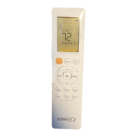
Explains the various icons and indicators on the controller's display screen for operation modes and settings.

Button Descriptions

Details the function of each button on the controller for mode selection, timing, and adjustments.

Operations and Settings

Start;Stop Operation

Instructions on how to turn the indoor unit on or off using the controller's power button.

Temperature Display Units

Guide on how to toggle between Fahrenheit and Celsius display for temperature settings.

Setting Operation Mode

Steps to select and change the operating mode (Auto, Cool, Dry, Heat, Fan) for the system.

Temperature Setting

Instructions on how to adjust the desired room temperature setpoint using the controller.

Timer Operations

Details on setting up automatic start (ON) and stop (OFF) timers for the indoor unit operation.

Troubleshooting

Fault Codes

Lists common fault codes displayed by the indoor unit and their corresponding error descriptions.

Overview

The Lennox Mini-Split Systems Wired Indoor Unit Controller (M0STAT61Q-1) is a wired controller designed for Lennox mini-split indoor units, providing installation and operation instructions for the system.

Function Description:

This controller serves as the primary interface for managing the operation of Lennox mini-split indoor units. It allows users to select various operating modes, adjust temperature setpoints, control fan speed, and set timed operations (Timer ON/OFF). The controller also features a "Follow Me" function, which transfers the temperature sensing function from the indoor unit to the controller's built-in sensor, allowing for more precise temperature control based on the controller's location. The display provides visual feedback on the current operating mode, fan speed, setpoint temperature, and any active timed operations or locked status.

Important Technical Specifications:

  • Input Voltage: 5VDC
  • Ambient Temperature Range: 23~110°F (-5~43°C)
  • Ambient Humidity Range: RH40%~RH90%
  • Cable Length: The controller cable length should not exceed 40 ft. (12 m).
  • Wiring: 5-conductor shielded cable.
  • Installation Requirements:
    • Must be installed indoors, not on outside walls or in direct sunlight.
    • Requires a minimum distance of 12" (305 mm) between low voltage control wire and high voltage power wires.
    • All wiring must conform to local and national building and electrical codes and ordinances.
    • Do not install in areas with heavy oil, vapor, or sulfur-containing gases.

Usage Features:

  • Operation Modes: Users can scroll through Auto, Cool, Dry, Heat, and Fan Only modes using the "Mode" button.
    • Auto Mode: System automatically selects cooling or heating based on setpoint and room temperature. (Note: Not recommended for multi-zone units to avoid conflict errors).
    • Cool Mode: System operates in cooling.
    • Dry Mode: System removes humidity based on preset conditions (fan speed and setpoint temperature are not adjustable in this mode).
    • Heat Mode: System operates in heating.
    • Fan Only Mode: Fan operates without heating or cooling.
  • Temperature Adjustment: "Up" and "Down" arrow buttons allow adjustment of the temperature setpoint.
  • Fahrenheit/Celsius Display: Simultaneously pressing and holding the "Up" and "Down" buttons for three seconds toggles between Fahrenheit and Celsius display.
  • Fan Speed Control: The "Fan Speed" button scrolls through Auto, Low, Med, and High fan speeds.
  • Timer ON/OFF:
    • Timer ON: Sets a delay (in half-hour increments up to 10 hours, then 1-hour increments) before the indoor unit begins operation.
    • Timer OFF: Sets a delay (in half-hour increments up to 10 hours, then 1-hour increments) before the indoor unit stops operation.
    • To modify settings, press the respective Timer ON/OFF button and adjust the time. Setting the timer to 0.0 turns off timed operation.
  • Follow Me Function: Activated by the "Follow Me" button, this feature uses the controller's built-in air temperature sensor instead of the indoor unit's sensor for temperature sensing.
  • Swing Function: The "Swing" button initiates or stops left and right louver oscillation. Louvers remain in place when stopped. (Availability may vary by indoor unit model).
  • Lock Function: The "Lock" button (accessed with a blunt-tipped device) locks or unlocks the current settings to prevent accidental changes.
  • Reset Function: The "Reset" button (accessed with a blunt-tipped device) cancels current settings and resets the controller to factory settings.
  • Power ON/OFF: The "ON/OFF" button turns the indoor unit on or off, indicated by the LED power button's brightness.
  • Economy Button: Not used in this model.

Maintenance Features:

  • Cleaning: Clean the controller using a clean, damp cloth. Do not spray cleanser directly on or around the controller.
  • Troubleshooting: The manual provides a comprehensive list of fault codes (Table 2) for both indoor and outdoor units, aiding in diagnosing system malfunctions. These codes cover issues such as EEPROM errors, communication errors, fan speed errors, sensor errors (return air, coil, ambient, discharge temperature), high/low voltage protection, low temperature lockout, compressor drive errors, mode conflicts, and high/low pressure switch issues.
  • Professional Installation/Service: Emphasizes that installation, adjustment, alteration, service, or maintenance must be performed by a licensed professional HVAC installer or service agency to prevent property damage, personal injury, or loss of life.
  • Wiring Access: The wall plate design allows for the controller cover to be removed for wiring access, and slack in the wiring should be provided for future maintenance.
  • Insulation Testing: Do not use a megger to test insulation.

Lennox M0STAT61Q-1 Specifications

General IconGeneral
BrandLennox
ModelM0STAT61Q-1
CategoryController
LanguageEnglish

Related product manuals