EasyManua.ls Logo

Lennox M0STAT120L-1

Lennox M0STAT120L-1
8 pages
To Next Page IconTo Next Page
Loading...
©
2023 Lennox Industries Inc.
Dallas, Texas, USA
M0STAT120L-1 Indoor
Wired Non-Programmable
Controller
CONTROLS
508331-01 6/2023
Table of Contents
General ................................................... 2
Requirements ......................................... 2
Shipping and Packing List ...................... 2
Product Overview ................................... 3
Product Dimensions ............................... 3
Back Plate Removal ............................... 3
Installing Back Plate on Drywall ............. 4
Making Connections ............................... 4
Wiring Diagram ..................................... 4
Cable Connection Illustration................ 4
Reattached the Top Panel ...................... 5
User Information ..................................... 5
Display Indicators ................................... 7
THIS MANUAL MUST BE LEFT WITH THE
OWNER FOR FUTURE REFERENCE
WARNING
Improper installation, adjustment, alteration,
ser vice or maintenance can cause property
damage, personal injury or loss of life.
Installation and service must be performed
by a li censed professional HVAC installer (or
equivalent) or a service agency.
INSTALLATION AND USER
INFORMATION GUIDE
Question and Answer IconNeed help?

Do you have a question about the Lennox M0STAT120L-1 and is the answer not in the manual?

Lennox M0STAT120L-1 Specifications

General IconGeneral
BrandLennox
ModelM0STAT120L-1
CategoryController
LanguageEnglish

Summary

General Safety Warning

General Information

Product Description

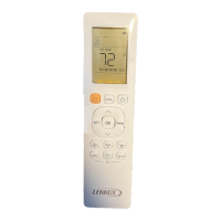
The MOSTAT120L-1 is a wired non-programmable controller for mini-split indoor units with timed schedules.

Installation Requirements

Power Supply Disconnection

Ensure power supply to the indoor unit is disconnected before installation. Controller should be used as described.

Shipping and Packing List

Package Contents

Details items included in Package 1 of 1, such as controller, guide, screws, anchors, and cables.

Product Overview

Key Features

Built-in memory, dimensions, LCD display, wiring requirements, and cable length specifications.

Product Dimensions

Back Plate Removal

Procedure

Step-by-step instructions for removing the back plate using a screwdriver, with PCB caution.

Installing Back Plate on Drywall

Making Connections

Wiring Diagram

Diagram illustrating electrical connections between controller, cable, and indoor unit.

Cable Connection Illustration

Guide for connecting the 5-pin cable assembly to the controller and indoor unit, including ground screw.

Reattaching the Top Panel

User Information

Fan Speed Control

How to use the FAN SPEED button to select fan speed settings like Auto, Low, Med., and High.

Mode Selection

Instructions on using the MODE button to cycle through operation modes like Auto, Cool, Dry, Heat, and Fan.

Function Button Operations

Explains how to use the FUNCTION button for operations like Turbo, Sleep, Active Clean, and Follow Me.

Swing Function Control

How to use the SWING button for louvre movement and to set desired air direction.

Timer Settings

Instructions for setting auto-on and auto-off sequences, with time increment details.

Power Control

Explains how to use the POWER button to turn the system on and off.

Confirmation and Navigation Buttons

Details the CONFIRM button for selecting functions and the BACK button for returning to the previous step.

Temperature and Unit Adjustment

How to adjust temperature and switch between Fahrenheit (°F) and Celsius (°C) using UP/DOWN buttons.

Locking Controller Settings

Instructions on how to lock and unlock controller settings using Function and Swing buttons.

Display Indicators

Icon Guide

Explanation of various icons displayed on the controller, including mode, fan speed, timer, and feature indicators.

Related product manuals