IOM / ROOF-TOP FLEXY™ Series - Page 17
AIR FLOW BALANCINGAIR FLOW BALANCING
AIR FLOW BALANCINGAIR FLOW BALANCING
AIR FLOW BALANCING
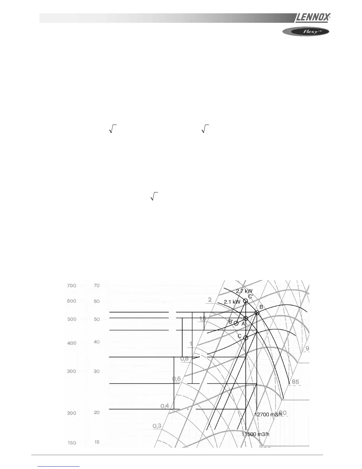
EXAMPLE :
You may want to adjust a FHK 120 set to 22 000 m
3
/h with a system resistance of 150Pa:
The machine has 2 fans (chart D).
For this operating point, the unit supplied is fitted with E kits comprising 112 mm - 131 mm variable pulleys on the motors
and 250 mm pulleys on the fans.
In this case the pulley motor adjustment is 126 mm for a fan speed of 730 rpm.
On the chart, for 11 000 m
3
/h (2 fans), indicates 730 rpm (point A).
• Total pressure 500 Pa
(150 Pa system pressure + 230 Pa equipment loss + 120 Pa static pressure)
• Absorbed power 2.1 kW, which gives 5.7 A, calculated as follows:
In = (P.kw x Ct / Rm ) / ( 3 x U x cos
ϕϕ
ϕϕ
ϕ) = ( 2100 * 1.2 / 0.8 ) / ( 3 x 400 x 0.8 ) = 5.7A
Rm = Motor output
Ct = Transmission coefficient
On site you measure :
• System static pressure 70 Pa or total pressure 230 Pa
(the pressure must be measured after 1 m minimun on the return ductwork)
• Absorbed power 6.8A
The theoretical absorbed power will be : P = (
3 x 400 x 6.8 x 0.8 ) / 0.8(Rm) x 1.2(Ct) = 2,500 W
With reference to the chart data, the operating point B has been highlighted as we note that: the system is exceeding
design airflow rates. 12 700 m
3
/h and 25 400 m
3
/h can be read for the two fans instead of the 22,000 m
3
/h specified.
To return to the design flow, consider point C, which now gives a rotation speed of 650 rpm, i.e. a variable pulley adjustment
of :
Adjustment = fan speed / motor speed * pulley diameter = 650 / 1450 * 250 = 112 mm.
Alternatively, where there is reduced airflow, i.e.caused by a greater system resistance than anticipated (items B’ and C’),
follow the same procedure, but in this case ensure that the absorbed power at C' is compatible with the motor fitted.
Pression dynamique
Pression statique demandée
Pression totale mesurée
Pression statique mesurée
730 RPM
650 RPM
 Loading...