Page 36 - IOM / Rooftop Smart and Linéa™ Range
OUTDOOR AIR DAMPEROUTDOOR AIR DAMPER
OUTDOOR AIR DAMPEROUTDOOR AIR DAMPER
OUTDOOR AIR DAMPER
The outdoor air damper section installs in the SMART range
to allow a fixed amount of outside air into the system. The
outdoor air damper replaces the unit side panel where a
downflow economiser would normally be installed. The
dampers may be manually adjusted and fixed in place to
allow up to 25 percent outside air into the system at all times.
The washable filter supplied with the outdoor air damper
can be cleaned with water and mild detergent.
APPLICATION
Optional outdoor air dampers provide up to 25 percent fresh
air for return.
Damper assembly is motorized : damper modulates
simultaneously with the blower during the occupied period
and remains closed during the unoccupied period (figure
47)
Damper assembly is manually operated : damper position
is manually set at installation and remains in that position
(see figures 48 & 49).
MOTORIZED DAMPER ASSEMBLY
1. Disconnect all power unit.
2. Release latches and open filter access panel.
3. Align bottom of damper assembly with support bracket
and slide assembly into unit (see figure 47).
4. Fit damper assembly end plate over end plate of
assembly and secure with retained screws.
5. Connect damper motor plug P3 to unit jack J3.
MANUAL DAMPER ASSEMBLY
SIZES 020 TO 045.
1. Disconnect all power to unit.
2. Release latches and open filter access panel.
3. Align damper assembly as shown in figure 48 and
slide assembly into unit.
4. Fit damper assembly end plate over en d of assembly
and secure with retained screws.
5. Loosen sheet metal screws on damper assembly en
d plate. Adjust to desired setting and tighten screws
(see figure 48).
MANUAL DAMPER ASSEMBLY
SIZES 055 TO 090.
1. Disconnect all power to unit.
2. Release latches and open filter access panel.
3. Align bottom of damper assembly with support bracket
and slide assembly into unit (see figure 49).
4. Fit damper assembly end plate over end of assembly
and secure with retained screws.
5. Loosen wing nuts on damper adjustment lever on
damper assembly end plate. Adjust to desired setting
and tighten wing nut (see figure 49).
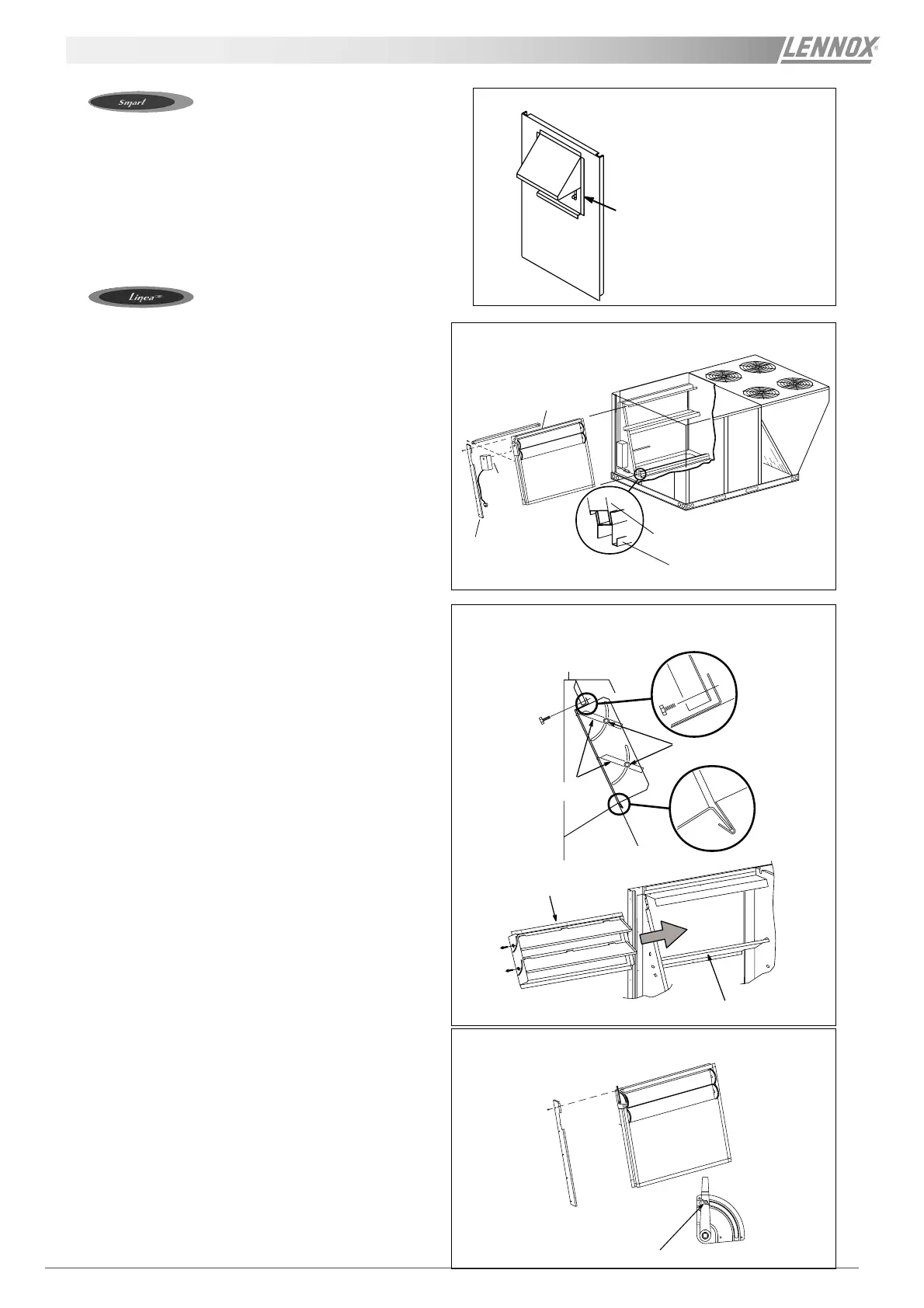
FRESH AIR DAMPER
Figure 46
Loosen screws and slide down to allow
more air into system
MOTORISED OUTDOOR AIR DAMPER
Figure 47
Damper assembly
Bottom damper assembly
Bottom support bracket
End plate
MANUAL OUTDOOR AIR DAMPER - UNITS 020 TO 045
Figure 48
SIDE VIEW
Sheet metal screws
Damper blades
Damper assembly
Unit division panel
Figure 49
MANUAL OUTDOOR AIR DAMPER - UNITS 055 TO 090
Loosen wing nut and adjust lever to
desired setting
 Loading...


