Page 44
10 - Back wash using steam. Begin from the burner
opening on each clam. Steam must not exceed
275°F.
11 - To clean burners, run a vacuum cleaner with a soft
brush attachment over the face of burners. Visually
inspect inside the burners and crossovers for any
blockage caused by foreign matter. Remove any
blockage. FIGURE 21 shows burner detail.
12 - To clean the combustion air inducer visually inspect
and using a wire brush clean where necessary. Use
compressed air to clean o debris and any rust.
13 - Reinstall heat exchanger in vestibule. (Replace the
ve screws in the cabinet from step 10 if removed).
14 - Reinstall collector box, combustion air assembly,
internal ue pipe and ue chase. Seal with high
temperature RTV. Reinstall all screws to the collector
box and combustion air inducer. Failure to replace
all screws may cause leaks. Inspect gaskets for any
damage and replace if necessary.
15 - Reinstall burner box, manifold assembly and burner
box cover.
16 - Reconnect all wires.
17 - Reconnect top cap and vent pipe to combustion air
inducer outlet.
18 - Reconnect gas supply piping.
19 - Turn on power and gas supply to unit.
20 - Set thermostat and check for proper operation.
21 - Check all piping connections, factory and eld, for
gas leaks. Use a leak detecting solution or other
preferred means.
CAUTION
Some soaps used for leak detection are corrosive
to certain metals. Carefully rinse piping thoroughly
after leak test has been completed. Do not use
matches, candles, ame or other sources of ignition
to check for gas leaks.
22 - If a leak is detected, shut gas and electricity o and
repair leak.
23 - Repeat steps 21 and 23 until no leaks are detected.
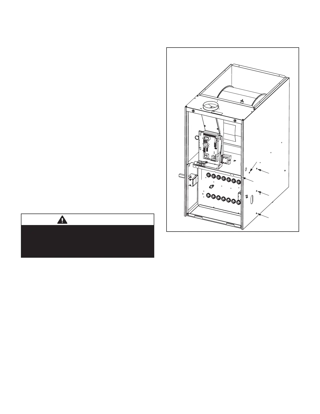
24 - Replace access panel
Remove five screws if necessary
(either side of cabinet)
1
2
3
4
5
FIGURE 22
VII- Wiring and Sequence of Operation
Integrated Control Self Check
When there is a call for heat, the integrated control runs a
self check. The control checks for S10 primary limit, S21
secondary limit (s) and S47 rollout switch normally closed
contacts. The control also checks for S102 high heat and
S128 low heat prove switch normally open contacts. Once
self check is complete and all safety switches are opera-
tional, heat call can continue.
NOTE - The ignition control thermostat selection DIP
switch is factory-set in the “TWO-STAGE” position.
 Loading...


