Page 36
8. Combustion Air Inducer (B6)
All units use a two-stage combustion air inducer to move
air through the burners and heat exchanger during heat-
ing operation. The blower uses a 120VAC motor. The mo-
tor operates during all heating operation and is controlled
by furnace / blower control A92. The inducer also operates
for 15 seconds before burner ignition (pre-purge) and for
5 seconds after the gas valve closes (post-purge). The in-
ducer operates on low speed during rst-stage heat, then
switches to high speed for second stage heat.
NOTE - Each furnace model uses a unique CAI. Refer to
Lennox Repair Parts listing for correct inducer for replace-
ment.
A pressure switch connected to the combustion air induc-
er orice plate is used to prove inducer operation. The
combustion air inducer orice will be dierent for each
model. See TABLE 16 for orice sizes. The switch mon-
itors air pressure in the inducer housing. During normal
operation, the pressure in the housing is negative. If pres-
sure becomes less negative (signifying an obstruction) the
proving switch opens. When the proving switch opens, the
furnace control (A92) immediately closes the gas valve to
prevent burner operation.
TABLE 16
Unit C.A.I. Orice Size
-070 1.375
-090 1.625
-110 1.844
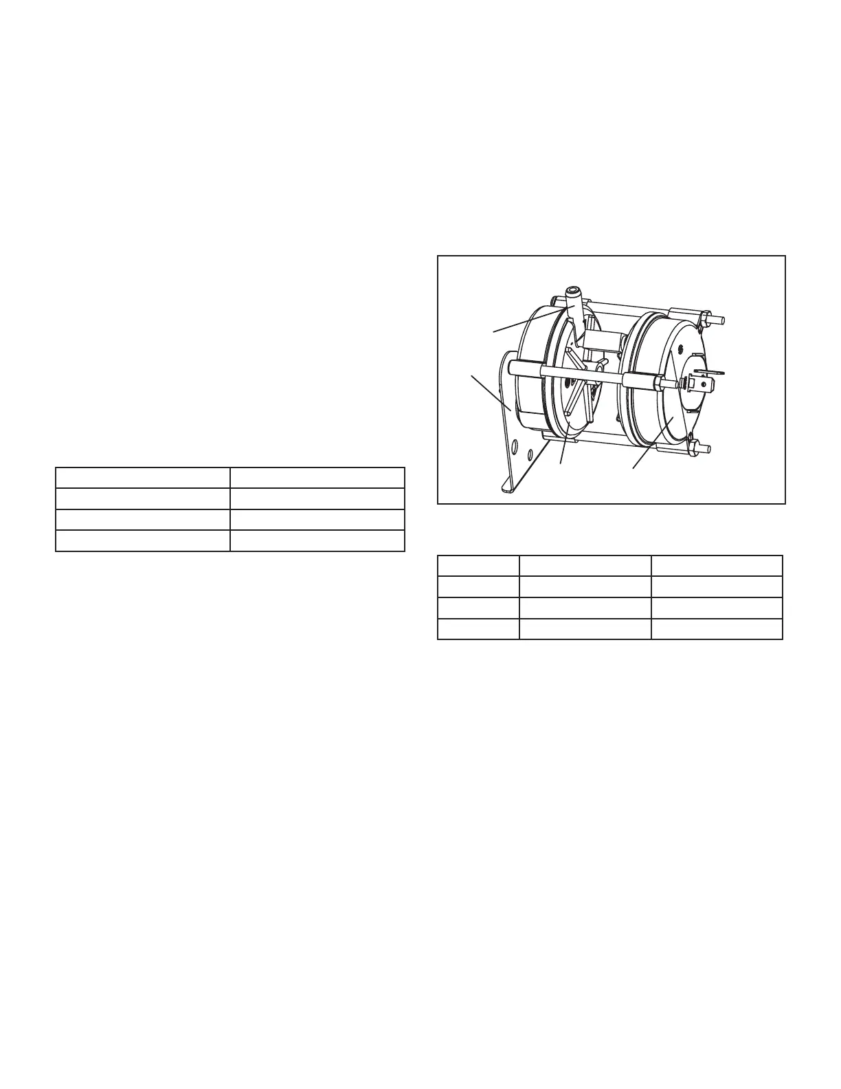
9. Combustion Air Inducer Pressure Switch (S18)
S18 is a dual combustion air pressure switch (rst and
second stage) located on the combustion air inducer or-
ice bracket. The switch is connected to the combustion
air inducer housing by means of a exible silicone hose.
It monitors negative air pressure in the combustion air in-
ducer housing.
The switches are a single-pole single-throw proving switch
electrically connected to the furnace control. The purpose
of the switch is to prevent burner operation if the com-
bustion air inducer is not operating or if the ue becomes
obstructed.
On heat demand (rst or second stage) the switch sens-
es that the combustion air inducer is operating. It closes
a circuit to the furnace control when pressure inside the
combustion air inducer decreases to a certain set point.
Set points vary depending on unit size.
See TABLE 17. The pressure sensed by the switch is neg-
ative relative to atmospheric pressure. If the ue becomes
obstructed during operation, the switch senses a loss of
negative pressure (pressure becomes more equal with at-
mospheric pressure) and opens the circuit to the furnace
control and gas valve. A bleed port on the switch allows
relatively dry air in the vestibule to purge switch tubing, to
prevent condensate build up.
NOTE - The switch is factory set and is not eld adjust-
able. It is a safety shut-down control in the furnace and
must not be by-passed for any reason. If switch is closed
or by-passed, the control will not initiate ignition at start up.
COMBUSTION AIR PRESSURE SWITCH
Tap
High Fire
Switch
Low Fire
Switch
Bracket
FIGURE 16
TABLE 17
Unit Set Point High Heat Set Point Low Heat
-070 0.55 0.20
-090 0.55 0.20
-110 0.60 0.25
II-PLACEMENT AND INSTALLATION
Make sure unit is installed in accordance with installation
instructions and applicable codes.
III-START-UP
A-Preliminary and Seasonal Checks
1 - Inspect electrical wiring, both eld and factory
installed for loose connections. Tighten as required.
2 - Check voltage at disconnect switch. Voltage must
be within range listed on the nameplate. If not,
consult the power company and have voltage
condition corrected before starting unit
 Loading...


