Page 41
V-TYPICAL OPERATING CHARACTERISTICS
A-Blower Operation and Adjustment
When the thermostat is set to “FAN ON,” the indoor blow-
er will run continuously at approximately 38% of the sec-
ond-stage cooling speed when there is no cooling or heat-
ing demand.
When the SL280DFV is running on high re or low re
(low re is 91% of high re), the indoor blower will run
on the heating speed designated by the positions of DIP
switches 11 and 12. When the SL280DFV is running on
second-stage cool or rst-stage cool (second-stage cool
is 70% of rststage cool), the indoor blower will run on the
cooling speed designated by the positions of DIP switches
5 and 6.
B-Temperature Rise
Temperature rise for SL280DFV units depend on unit in-
put, blower speed, blower horsepower and static pressure
as marked on the unit rating plate. The blower speed must
be set for unit operation within the range of “TEMP. RISE
°F” listed on the unit rating plate for high re and low re.
To Measure Temperature Rise:
1 - Place plenum thermometers in the supply and
return air plenums. Locate supply air thermometer
in the rst horizontal run of the plenum where it will
not pick up radiant heat from the heat exchanger.
2 - Set thermostat to highest setting. Conrm unit is on
high re by checking rate.
3 - After plenum thermometers have reached their
highest and steadiest readings, subtract the two
readings. The dierence should be in the range
listed on the unit rating plate. If the temperature is
too low, decrease blower speed.
4 - Repeat on low re. Do not adjust low re manifold
pressure.
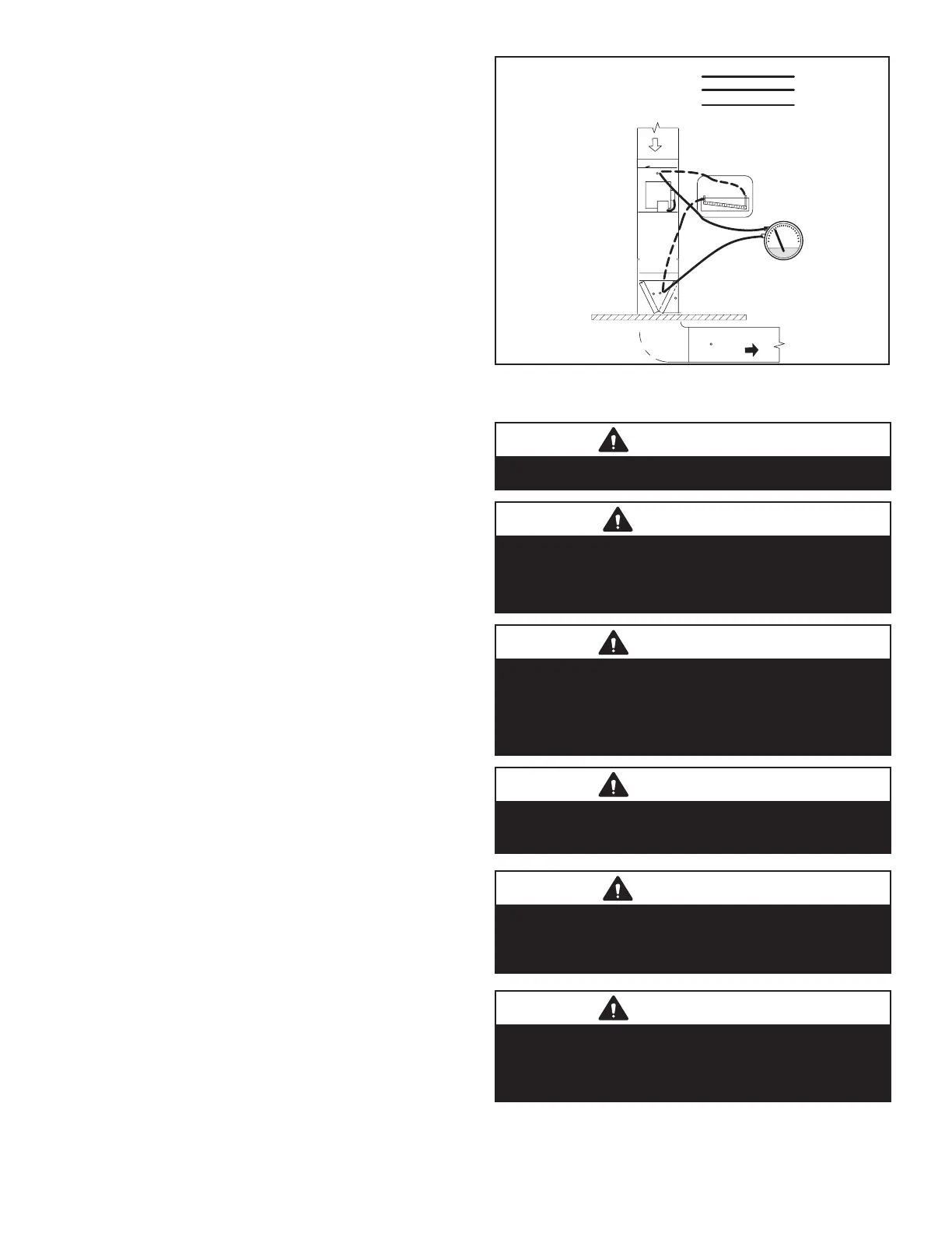
C-External Static Pressure
1 - Tap locations shown in FIGURE 20.
2 - Punch a 1/4” diameter hole in supply and return
air plenums. Insert manometer hose ush with
inside edge of hole or insulation. Seal around the
hose with permagum. Connect the zero end of the
manometer to the discharge (supply) side of the
system. On ducted systems, connect the other end
of manometer to the return duct as above. Open all
return air registers and check for clean lter.
3 - With only the blower motor running and the
evaporator coil dry, observe the manometer
reading. Adjust blower motor speed to deliver the
air desired according to the job requirements. For
heating speed external static pressure drop must
not be more than 0.8” W.C. For cooling speed
external static pressure drop must not be more than
1.0” W.C.
4 - Seal the hole when the check is complete.
Supply Duct Static
Return Duct Static +
Total Duct Static =
(dry coil)
Return
Supply
High “+”
Low “-”
+
−
or
FIGURE 20
VI-MAINTENANCE
WARNING
Disconnect power before servicing unit.
CAUTION
Label all wires prior to disconnection when servicing
controls. Wiring errors can cause improper and
dangerous operation. Verify proper operation after
servicing.
WARNING
The inner blower access panel and vent pipe must be
securely in place when the blower and burners are
operating. Gas fumes, which could contain carbon
monoxide, can be drawn into living space resulting
in personal injury or death.
WARNING
Electric Shock Hazard. Can cause injury or death.
Unit must be properly grounded in accordance with
national and local codes.
CAUTION
Failure to use properly sized wiring and circuit
breaker may result in property damage. Size wiring
and circuit breaker(s) per Product Specications
bulletin (EHB) and unit rating plate.
WARNING
Fire Hazard. Use of aluminum wire with this product
may result in a re, causing property damage,
severe injury or death. Use copper wire only with
this product.
 Loading...


