Page 54
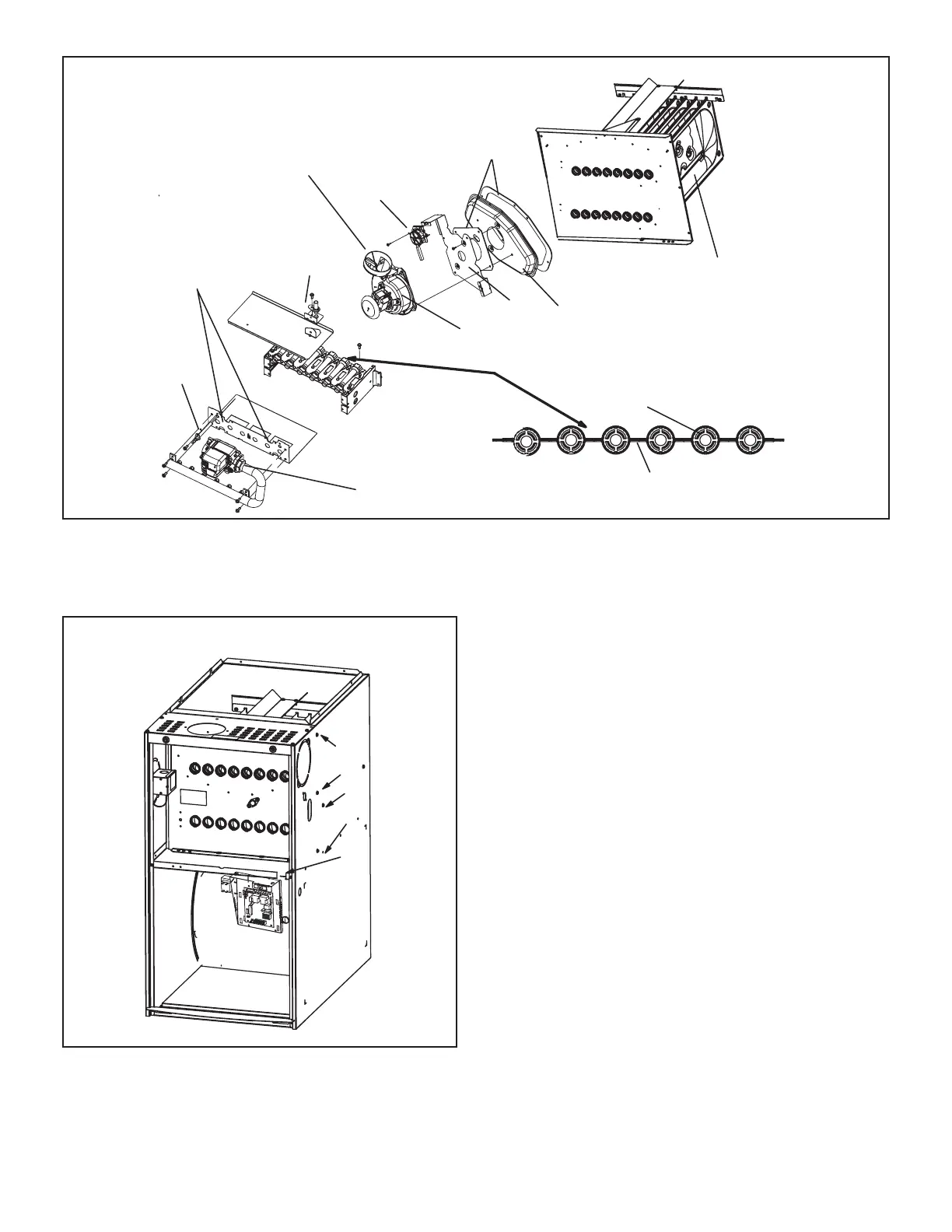
BURNER, COMBUSTION AIR INDUCER ASSEMBLY
&
HEAT EXCHANGER REMOVAL
Heat Exchanger
Gasket
Collector Box
Orifice Plate
Flue Transition
Pressure Switch
Combustion Air Inducer
Manifold And Gas Valve
Retention Rings
Cross Over
Ignitor
Flame
Sensor
Rollout Switches
FIGURE 25
Remove 5 screws if necessary
(either side of cabinet)
1
2
3
4
5
FIGURE 26
VII- Wiring and Sequence of Operation
Integrated Control Self Check
When there is a call for heat, the integrated control runs a
self check. The control checks for S10 primary limit, S21
secondary limit (s) and S47 rollout switch normally closed
contacts. The control also checks for S102 high heat and
S128 low heat prove switch normally open contacts. Once
self check is complete and all safety switches are opera-
tional, heat call can continue.
NOTE - The ignition control thermostat selection DIP
switch is factory-set in the “TWO-STAGE” position.

 Loading...


