EasyManua.ls Logo

Lennox XP25-036-230-01 User Manual

Lennox XP25-036-230-01
89 pages
To Next Page IconTo Next Page
Page #1 background imageLoading...
Page #1 background image
Page 1
2013 Lennox Industries Inc.
Corp. 1252-L11
July 24, 2013 (Revised on Dec. 11, 2014)
XP25
INSTALLATION AND SERVICE
PROCEDURE
Service Literature
Dave Lennox Signature
®
Collection XP25 Series Units
IMPORTANT
This unit has refrigerant piping requirements that are
unique to this this model. Size and install the refrigerant
piping per table 2 (page 14) to ensure proper unit operation.
This unit is an integral component of a system that requires an
iComfort Wi-Fi
®
thermostat and iComfort
®
-enabled air handler
or furnace.
XP25 Heat
Pump
iComfort Wi-Fi
®
Thermostat
iComfort
-enabled
air handler or
furnace
IMPORTANT: Before applying any power (main, solar or low
voltage) to the outdoor unit, confirm iComfort Wi-Fi
®
thermostat
has Version 2.1 or higher software. (Reference iComfort Wi-Fi
®
thermostat manual.)
WARNING
Improper installation, adjustment, alteration, service or
maintenance can cause personal injury, loss of life, or
damage to property. Installation and service must be
performed by a licensed professional installer (or
equivalent) or a service agency.
TABLE OF CONTENTS
I. OVERVIEW
Model Number Identification 2....................
Typical Serial Number Identification 2..............
Specifications 2.................................
Electrical Data 3................................
Unit Dimensions 4..............................
Typical Unit Parts Arrangement 5.................
General 7......................................
Operating Service Valves 7.......................
II. INSTALLATION
Unit Placement 9...............................
Removing and Installing Panels 12.................
New or Replacement Line Set 13..................
Brazing Connections 16...........................
Flushing the System 19...........................
Leak Testing the System 21.......................
Evacuating the System 21.........................
Electrical 24.....................................
Servicing Unit Delivered Void of Charge 29..........
Unit Start-Up 29.................................
III. SYSTEM OPERATION AND SERVICE
7-Segment Alert and System Status Codes 30.......
Outdoor Control Push-Button Operation 38..........
Configuring Unit 42...............................
Reconfiguring Outdoor Control using iComfort Wi-Fi
®
Thermostat 43...................................
System Overview 43.............................
Diagnostic Information 43.........................
Defrost Function 43..............................
Outdoor Temperature Operational Range 44.........
Maintenance 45..................................
SunSource
®
Home Energy System 45..............
Unit Wiring Diagrams 46..........................
Factory Wiring Diagrams 49.......................
Unit Sequence of Operations 51...................
Component Testing 56............................
System Refrigerant 85............................
IMPORTANT
The Clean Air Act of 1990 bans the intentional venting of
refrigerant (CFCs, HCFCs AND HFCs) as of July 1, 1992.
Approved methods of recovery, recycling or reclaiming
must be followed. Fines and/or incarceration may be
levied for noncompliance.

Table of Contents

Question and Answer IconNeed help?

Do you have a question about the Lennox XP25-036-230-01 and is the answer not in the manual?

Lennox XP25-036-230-01 Specifications

General IconGeneral
Model NumberXP25-036-230-01
CategoryAir Conditioner
Phase1
Refrigerant TypeR-410A
Cooling Capacity36, 000 BTU
Voltage230V
Heating Capacity36, 000 BTU/h
Dimensions (Outdoor Unit)35"

Summary

I. OVERVIEW

Model and Serial Number Identification

Details on identifying model and serial numbers.

Specifications and Electrical Data

Lists technical specifications and electrical requirements for the units.

Unit Dimensions and Parts Arrangement

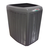
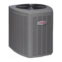
Shows physical dimensions, mounting, and component layout.

Operating Service Valves

Explains the function and operation of service valves.

II. INSTALLATION

Unit Placement and Clearances

Covers unit location, clearance requirements, and mounting considerations.

Panel Removal and Line Set Preparation

Instructions for removing panels and preparing refrigerant lines.

Refrigerant Line Set Installation

Details on installing or replacing refrigerant line sets.

Brazing, Flushing, and Leak Testing

Procedures for brazing, flushing, and leak testing the system.

System Evacuation

Details the procedure for evacuating the refrigerant system to a deep vacuum.

III. SYSTEM OPERATION AND SERVICE

Alerts, Status Codes, and Push-Button Operation

Explains diagnostic codes and control operation via buttons.

Unit Configuration and Control Setup

Guides on setting unit selection and reconfiguring via thermostat.

Compressor Protection and Defrost Functions

Details compressor lockout, defrost, and operational ranges.

Maintenance and Wiring Diagrams

Covers routine maintenance and electrical connection diagrams.

Unit Sequence of Operations

Illustrates the operational flow of the unit under various conditions.

Component Testing Overview

Details testing procedures for various system components.

Pressure Switches, Reversing Valve, and Compressor

Explains testing for pressure switches, reversing valve, and compressor.

Crankcase Heater, Filter Drier, and Expansion Valve

Details testing for crankcase heater, filter drier, and expansion valve.

Top Cap Switch, Reactors, and Line Filter

Covers testing for top cap switch, reactors, and line filter.

Outdoor Fan, Sensors, and Inverter Control

Details operation and testing for fan, sensors, and inverter control.

System Refrigerant Charging and Airflow

Procedures for charging refrigerant and checking indoor airflow.

Related product manuals