5 Electrical Connection Lenord + BauerLead/Connector pin assignment
30 GEL 2442
English
GEL
214
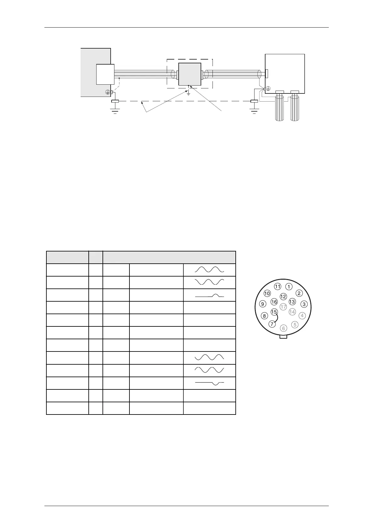
Interpolation electronics
(optional)
Evaluation
electronics
Machine
Mini-
Coder
Control lines
Potential
equalization line
Under unfavourable conditions
only, as very long cables and
extreme levels of interference
Electrical contact
enclosure/mounting plate
via tooth lock washer
Signal and control lines must be passed away from electric power cables; if that is
not possible use screened twisted pair cables and/or pass the encoder lines in iron
pipes.
With electrically isolated spindle rotor provide a measure for charge equilisation
between rotor and stator, e.g. by using antistatic brushes
Make sure that surge protective measures have been carried out externally (EN
61000–4–5).
5.3 Lead/Connector pin assignment
Lead colour Pin Signal/ function
white 1 U
1+
Track 1
brown 2 U
1–
/Track 1
grey 3 U
N+
Referencetrack
blue 7 0 V GND
– 8 + Temperature + (brown)
– 9 – Temperature – (blue)
red 10 U
B
+ 5 V
rose 11 U
2+
Track 2
black 12 U
2-
/Track 2
yellow 13 U
N-
Referencetrack
– 15 0 V GND Wire strap to 7
green 16 U
Sense
5 V Sense
Lead/connector pin as-
signment
Shield is not connected in-
side the MiniCoder