15. Make sure that all cables avoid the fan connectors and the power-backplane
system-board connector (see “Power-backplane-board connectors” on page 10
and “System-board internal cable connectors” on page 11).
16. Install the fan-bracket assembly.
17. Install the cover (see “Installing the cover” on page 57).
18. Slide the server into the rack.
19. Reconnect the external cables; then, reconnect the power cords and turn on
the peripheral devices and the server.
Attention: In a dc power environment, only trained service personnel other
than Lenovo service technicians are authorized to connect or disconnect power
to the dc power supply. See the documentation that comes with each dc power
supply.
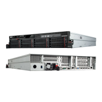
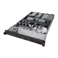
Installing a SCSI tape drive in a 2.5-inch model server
The tape drive installs in the tape-drive bay. See the documentation that comes with
the tape enablement kit for the original tape drive for instructions for mounting the
tape drive on the tape-drive tray.
1 Signal cable
2 Power cable
To install a SCSI tape drive in a 2.5-inch model server, complete the following
steps:
1. If you installed the space filler from the tape enablement kit onto the tape-drive
assembly, remove it now.
2. Remove the fan-bracket assembly.
3. Connect the tape drive signal and power cables to the back of the tape drive.
4. Make sure that the SCSI terminator is attached to the inside top of the
tape-drive bay as shown in the following illustration. If necessary, press the
terminator onto the corresponding hook-and-loop fastener on the inside top of
the bay.
86 ThinkServer RD120 server Machine Types 6444, 6445, 6446, and 6447: Hardware Maintenance Manual
 Loading...