CMVPFB01A 16
Cyclic Data Access - Dout Mapping
5.4 Cyclic Data
5.4.1 Overview
The control and status words allow the digital control and monitoring of the drive to be implemented using
a single data word for each function. Each bit in the control word has a particular function and provides
a method of controlling the output functions of the drive, such as run and direction. Each bit in the status
word provides feedback about the drive’s state of health and operational condition, such as drive healthy,
drive at speed, etc. The various Network Setpoints provide a method of editing the drives’ Frequency,
Speed, Toruque or PID control etc.
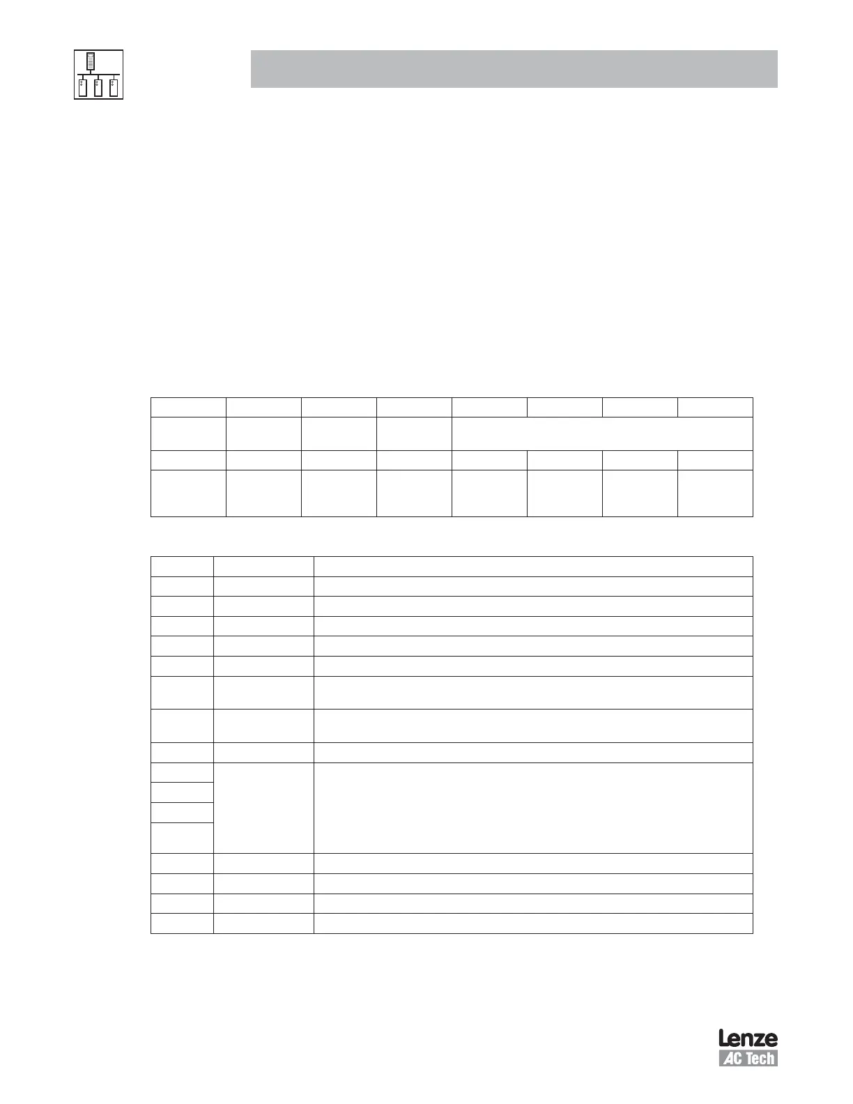
5.4.2 P44x = 1, SMV Control Word
The SMV Control Word consists of 16 control bits some of which are reserved.
Table 10: SMV Control Word
b15 b14 b13 b12 b11 b10 b9 b8
DC
Braking
PID
Disable
Quick
Stop
Controller
Inhibit
Network Setpoint Reference Source
b7 b6 b5 b4 b3 b2 b1 b0
Reserved Network
Reference
Enable
Network
Control
Enable
Reserved Reserved Fault
Reset
Run
Reverse
Run
Forward
Table 11: SMV Control Word BIT Functions
BIT Function Description
0 Run Forward Set to 1 to run the motor in the FORWARD direction.
1 Run Reverse Set to 1 to run the motor in the REVERSE direction.
2 Fault Reset A 0-to-1 transition will reset the drive from a trip condition.
3 Reserved
4 Reserved
5 Network Control
Enable
0 = Local Control
1 = Network Control
6 Network Reference
Enable
0 = Local Speed Reference
1 = Network Speed Reference
7 Reserved
8
Network
Setpoint
Reference
Source
0 = Network 4 = Preset #1 8 = Preset #5
1 = Keypad 5 = Preset #2 9 = Preset #6
2 = 0-10VDC 6 = Preset #3 10 = Preset #7
3 = 4-20mA 7 = Preset #4 11 = MOP
9
10
11
12 Controller Inhibit Set to 1 to disable the drive and allow the motor to coast to a stop
13 Quick Stop Set to 1 to disable the drive and stop the ramp time defined in P127
14 PID Disable When using PID mode, setting this bit (14) to 1 will disable PID control. (Active only in Network Control)
15 DC Braking Set to 1 to activate DC injection braking. Refer to P174 for details.