Code table
10
Function library
10.20
L
10.20-38
EDS82EV903-1.0-11/2002
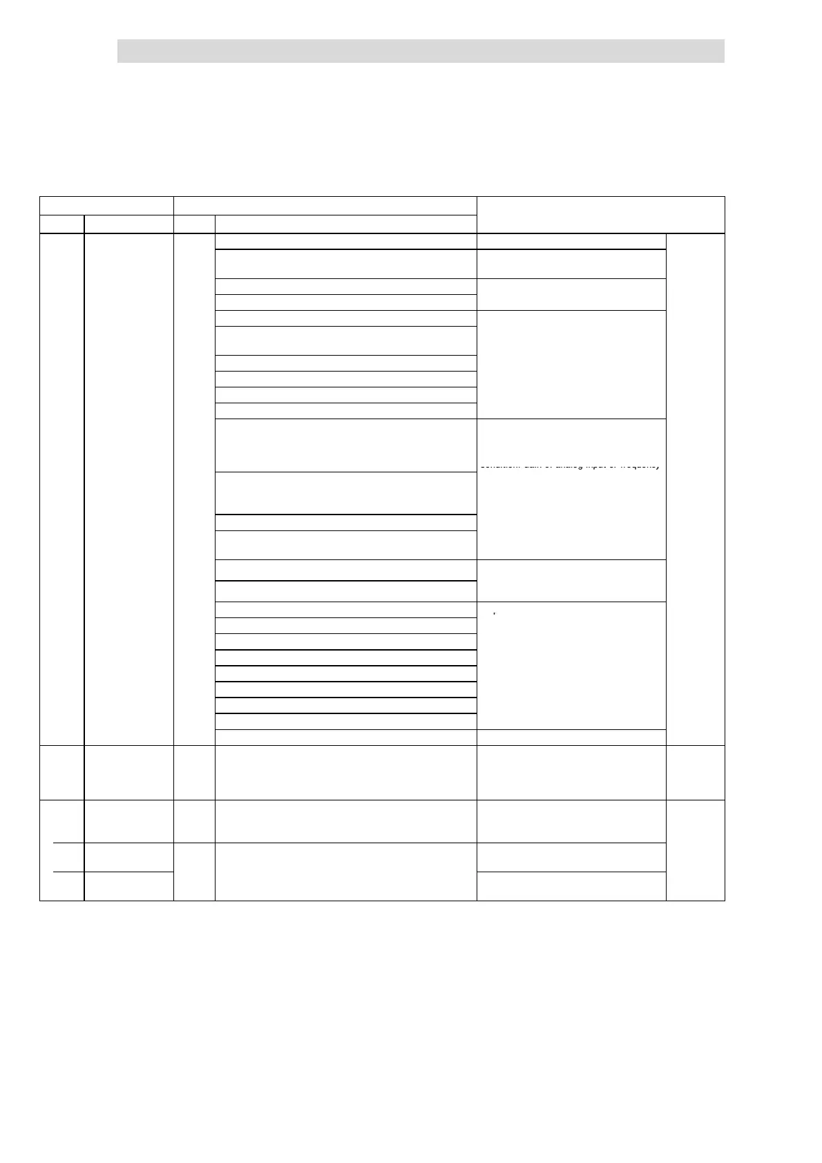
Code IMPORTANTPossible settings
No. SelectionLenzeName
C0419 Possible analog signals for C0419 ^ 10.12-4
v
(cont.)
26 Output frequency normalised without s lip
(MCTRL1-NOUT-NORM)
27 Output frequency without slip (MCTRL1-NOUT)
6V/12mA/5.85kHz ≡ C0011
28 Act. process controller value (PCTRL1-ACT)
29 Process controller setpoint (PCTRL1-SET1)
6V/12mA/5.85kHz ≡ C0011
30 Process controller output without precontrol
(PCTRL1-OUT)
31 Ramp function generator input (NSET1-RFG1-IN)
32 Ramp function generator output (NSET1-NOUT)
33 (A ) PID controller output (PCTRL1-PID-OUT)
34 (A ) Process controller output (PCTRL1-NOUT)
35 Input signal at X3/8 (Standard-I/O) or X3/1U or
X3/1I (Application-I/O), evaluated with gain
(C0414/1 or C0027) and offset (C0413/1 or
C0026) (AIN1-OUT)
6V/12mA/5.85kHz ≡ Maximum value
analog input signal (5 V, 10 V, 20 mA,
10 kHz)
Condition: Gain of analog input or frequency
36 Input signal at frequency input X3/E1,
evaluated with gain (C0426) and offset (C0427)
(DFIN1-OUT)
input set to:
C0414/x, C0426 = 100 %
37 Motor potentiometer output⋅(MPOT1-OUT)
38 (A ) Input signal at X3/2U or X3/2I, evaluated with
gain (C0414/2) a nd of fset (C0413/2) (AIN2-OUT)
40 AIF input word 1 (AIF-IN.W1)
Setpoint to drive from communication
41 AIF input word 2 (AIF-IN.W2)
mo
u
e
o
10 V/20 mA/10 kHz ≡ 1000
50 CAN-IN1.W1 or FIF-IN.W1
Setpoints to drive from function module to
51 CAN-IN1.W2 or FIF-IN.W2
FIF
52 CAN-IN1.W3 or FIF-IN.W3
10
20 m
10
Hz ≡ 1000
53 CAN-IN1.W4 or FIF-IN.W4
60 CAN-IN2.W1
61 CAN-IN2.W2
62 CAN-IN2.W3
63 CAN-IN2.W4
255 Not assigned (FIXED-FREE)
C0420* Gain analog output
X3/62
(AOUT1-GAIN)
Standard I/O
128 0 {1} 255 128 ≡ Gain 1
C0420 and C0108 are the same
^ 10.12-4
C0420*
(A)
63
Gain analog output s
Applicat ion I/O
128 ≡ Gain 1
^ 10.12-4
1 X3/62
(AOUT1-GAIN)
128
0 {1} 255 C0420/1 and C0108 are the same
2 X3/63
(AOUT2-GAIN)