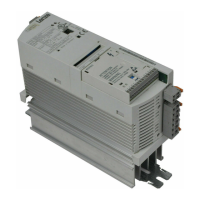
Do you have a question about the Lenze E82EV751K4C and is the answer not in the manual?
Crucial safety guidelines and best practices for installing and operating Lenze controllers.
Essential safety precautions and application guidelines for Lenze motors.
Identifies potential dangers and hazards associated with the product during operation.
Detailed technical specifications for normal operation at rated power.
Specific technical data for 230 V mains voltage operation.
Specific technical data for 400 V mains voltage operation.
Specific technical data for 500 V mains voltage operation.
Installation instructions for basic units within the 0.25 to 2.2 kW power range.
Instructions for installing units using the thermally separated push-through technique.
Guidelines for mounting units using the cold plate technique for heat dissipation.
Installation instructions for basic units within the 3 to 11 kW power range.
Instructions for installing units using the thermally separated push-through technique.
Guidelines for mounting units using the cold plate technique for heat dissipation.
Installation instructions for basic units within the 15 to 30 kW power range.
Instructions for installing units using the thermally separated push-through technique.
Guidelines for mounting units using the cold plate technique for heat dissipation.
Installation instructions for basic units within the 45 to 55 kW power range.
Instructions for installing units using the thermally separated push-through technique.
Installation instructions for basic units within the 75 to 90 kW power range.
Instructions for installing units using the thermally separated push-through technique.
Critical safety instructions for protecting personnel during wiring operations.
Guidelines for protecting the motor during wiring and operation.
Fundamental principles and requirements for wiring to ensure EMC compliance.
Wiring instructions for basic units within the 0.25 to 2.2 kW power range.
EMC-compliant wiring procedures for CE-typical drive system installations.
Detailed instructions for making power connections to the 230 V mains supply.
Detailed instructions for making power connections to the 400 V mains supply.
Instructions for connecting the motor and any external brake resistor.
Wiring instructions for basic units within the 3 to 11 kW power range.
EMC-compliant wiring procedures for CE-typical drive system installations.
Detailed instructions for making power connections to the 230 V mains supply.
Detailed instructions for making power connections to the 400 V mains supply.
Instructions for connecting the motor and any external brake resistor.
Wiring instructions for basic units within the 15 to 30 kW power range.
EMC-compliant wiring procedures for CE-typical drive system installations.
Detailed instructions for making power connections to the 400/500 V mains supply.
Wiring instructions for basic units within the 45 to 55 kW power range.
EMC-compliant wiring procedures for CE-typical drive system installations.
Detailed instructions for making power connections to the 400/500 V mains supply.
Wiring instructions for basic units within the 75 to 90 kW power range.
EMC-compliant wiring procedures for CE-typical drive system installations.
Detailed instructions for making power connections to the 400/500 V mains supply.
Information on function modules and terminal assignments for basic units (0.25-2.2 kW).
Information on function modules and terminal assignments for basic units (3-11 kW).
Wiring instructions for the KSR relay output, specifically for the 'Safe standstill' function.
Information on function modules and terminal assignments for basic units (15-90 kW).
Wiring instructions for the KSR relay output, specifically for the 'Safe standstill' function.
Essential checks and preparations required before initial power-on and commissioning.
Guidance on selecting the appropriate control mode (V/f, Vector, Sensorless Torque).
Procedure for modifying and saving parameter values using the keypad.
Procedure for modifying and saving parameter values using the XT EMZ9371BC keypad.
Selection and configuration of different controller operating modes.
Methods and parameters for optimizing the drive's operating behavior.
Describes controller behavior during mains interruptions or inhibit signals.
Configuration of start conditions and the flying-restart circuit for automatic synchronization.
Explanation and activation of the controller inhibit function for stopping power outputs.
Procedure for controlled motor deceleration to standstill following a mains failure.
Setting operational limits for speed, current, and other parameters.
Parameters for controlling acceleration, deceleration, braking, and stopping behavior.
Configuration of acceleration/deceleration times and S-shaped ramp profiles.
Configuration and activation of the quick stop function for rapid deceleration.
Configuration of analog inputs/outputs and digital signals for setpoints and actual values.
Function to automatically detect motor data and cable influences for optimal performance.
Configuration and operation of the process controller for various control loops.
Monitoring motor temperature using I2t or PTC sensors for protection.
Using I2t monitoring to thermally protect self-ventilated motors.
Connecting PTC resistors or thermostats for motor temperature monitoring and earth-fault detection.
Evaluating and handling external faults to ensure system monitoring.
Managing parameter sets, including restoring defaults, saving, and copying.
Procedures for saving custom settings and copying parameter sets between controllers.
General troubleshooting steps, including LED status and error analysis.
Methods for analyzing and retrieving error messages stored in the history buffer.
Procedures for identifying and resolving common errors and maloperations.
Troubleshooting common maloperations of the drive, including causes and remedies.
A guide to interpreting and resolving error messages displayed on the keypad or via Global Drive Control.
Instructions for resetting TRIP error messages after resolving the cause.
Essential conditions for ensuring reliable operation of networked drive systems.
Concepts for protecting controllers and preventing damage in DC-bus operation.
Details on braking operation with three-phase AC motors, including brake rectifiers.
Information on using external brake resistors for larger inertia or generator mode braking.
Configuration and implementation of speed control using inductive sensors.
Detailed signal processing within specific function blocks.
| Power Rating | 0.75 kW |
|---|---|
| Rated Power | 0.75 kW |
| Output Power | 0.75 kW |
| Output Current | 2.2 A |
| Protection Class | IP20 |
| Input Voltage | 380 ... 480 V |
| Input Frequency | 50/60 Hz |
| Control Method | Vector Control |
| Communication Interface | CANopen |


