Basics for wiring according to EMC
Installation in the control cabinet
6
Basic unit wiring
6.3
6.3.3
L
6.3-3
EDS82EV903-1.0-11/2002
l
The cables of the analog and digital inputs and outputs must be shielded. If
short (up to 200 mm), unshielded cables are used, they must be twisted.
l In case of the analog cables the shield must be connected to one side of
the controller.
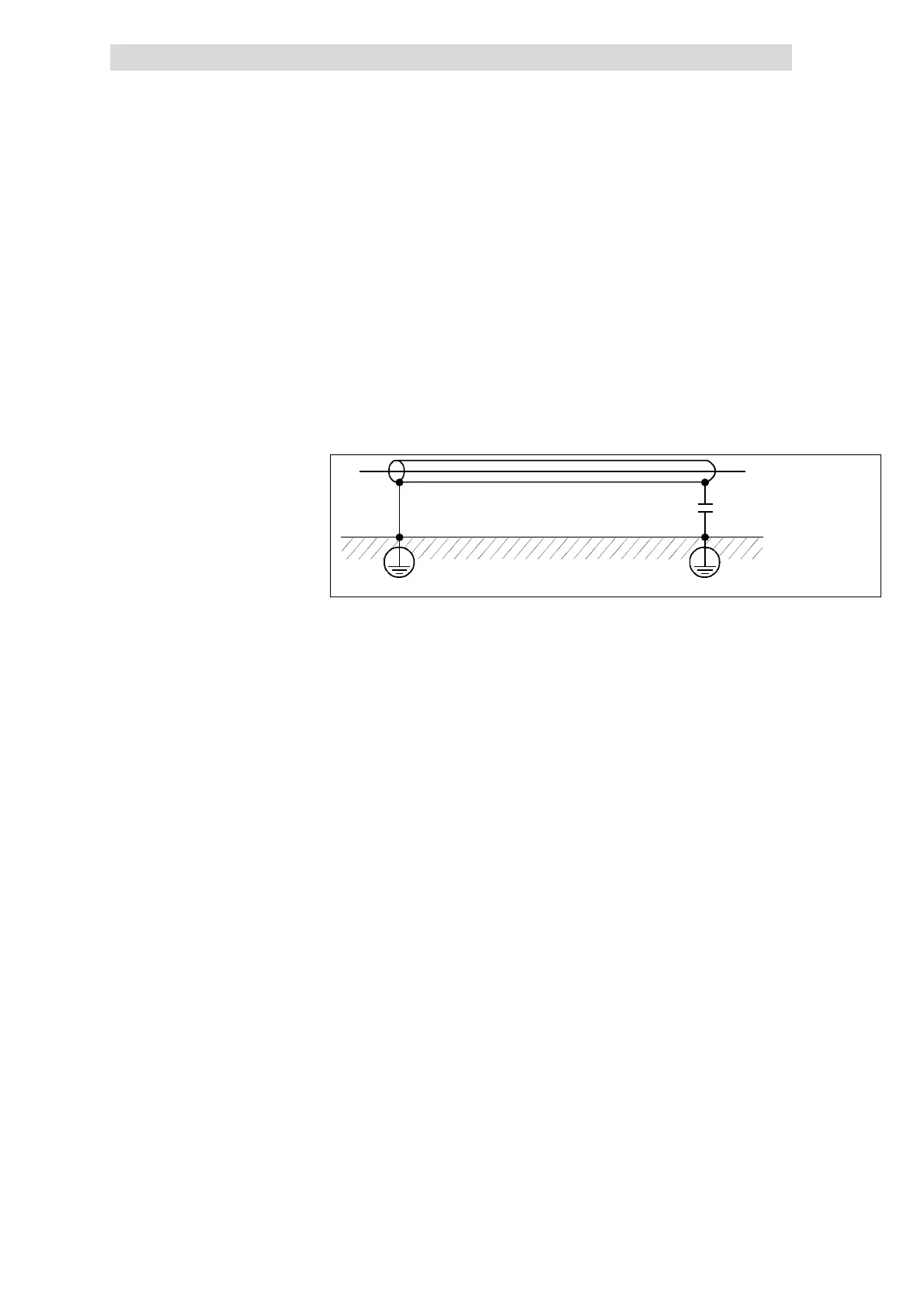
l In unfavorable conditions (very long cable, high interferences) it is possible
in case of analog cables to connect one shield end to PE via a capacitor
(e.g. 10 nF/250 V) to have a better shielding effect (see sketch).
l In case of digital cables the shield must be connected to both sides.
l The shields of the control cables must have a minimum distance of 50 mm
to the shield connections of the motor cables and DC cables.
Fig. 6.3-2 Shielding of long, analog control cables
6.3.3 Installation in the control cabinet
l Only use mounting plates with electrically conductive surface (zinc-coated
or V2A).
l Varnished mounting plates are unsuitable, even if the varnish is removed
from the contact surfaces.
l When using several mounting plates, make a conductive connection over a
large surface (e.g. using grounding strips).
l Connect the controller and RFI filter to the grounded mounting plate with a
surface as large as possible.
l No DIN rail mounting!
Control cables
Mounting plate requirements
Mounting of the components