Function block library
7-55
SHB9300CRV EN 2.0
Byte 1, 2, 3 and 4
The meaning of these user data can be selected among different signal types. Depending on the
requirement, these data can be evaluated as up to 2 analog signals, 32 digital signals or one phase
signal.Mixed forms are also possible.
Byte 5 and 6
form the signal to CAN-IN2.W3.
Byte 7 and 8
form the signal to CAN-IN2.W4.
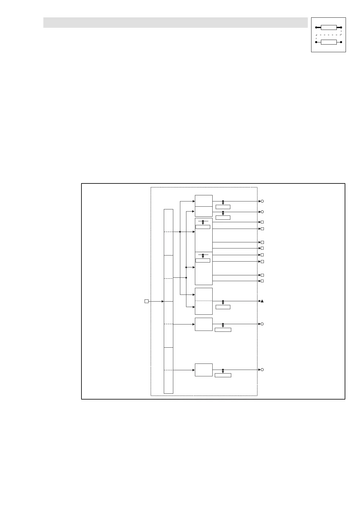
CAN-IN3
Theprocessdataobject CAN-IN3is provided for theevent-driventransmission of process dataand
for communication among the controllers. However, decentralized inputs can also be evaluated.
16 Bit
16 Bit
CAN-IN3.W 1
CAN-IN3.W 2
16 binary
signals
16 B it
Low W ord
16 Bit
High W ord
16 binaryi
signals
16 Bit
CAN-IN3.W 3
CAN-IN3.B15
CAN-IN3.B0
CAN-IN3.D1
B y te 3 ,4
B y te 5 ,6
B y te 7 ,8
System bus
X4
CAN-IN3
Bit 0
Bit 15
CAN-IN3.B14
CAN-IN3.B1
CAN-IN3.B31
CAN-IN3.B16
CAN-IN3.B30
CAN-IN3.B17
......
C 0867/3
C 0866/10
C 0866/8
C 0863/5
C 0863/6
C 0866/9
B y te 1 ,2
16 Bit
CAN-IN3.W 4
C 0866/11
Fig. 7-46 System bus (CAN-IN3)
 Loading...