Mechanical installation
Preparation
Mounting the gearboxes
4
23
Lenze ¯ MA 12.0013 ¯ 3.0
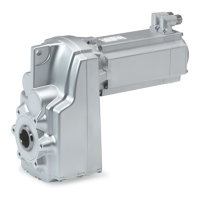
4.3.4 Mounting the gearboxes
Stop!
Shocks and impacts on the shaft damage the roller bearings.
¯ Draw the transmission elements onto the output shaft only by using the
centering thread.
¯ Align the gearbox shaft and transmission elements in an accurate fashion in order
to prevent tensioning.
¯ Mount belt pulleys, sprockets, or gear wheels as closely as possible to the gearbox
in order to keep the bending load of the shaft and the bearing forces at a
minimum level.
Gearbox with output flange
¯ Especially with regard to applications with an alternating load, Lenze
recommends...:
– the use of anaerobic adhesive between the gearbox flange and mounting area
in order to increase the friction fit;
– with steel or cast iron output flanges, the use of screws with a strength of 10.9
with correspondingly high tightening torques.
4.3.5 Maximum permissible load at the mounting flange
N version
Stop!
¯ The loads generated by the motor mounted must be checked!
¯ The forces F
M
mentioned (see following tables) at the mounting flange
must not be exceeded!
For the effective force F
M
, static forces (e.g. weight) and dynamic forces (e.g.
acceleration forces, for example caused by vibrations or start−up processes) have to be
taken into consideration.
Furthermore the loading case of the force F
M
has to be taken into consideration:

 Loading...