Mechanical installation
Preparation
Maximum permissible load at the mounting flange
4
24
Lenze ¯ MA 12.0013 ¯ 3.0
Loading case k
loading
case
Static 1
Dynamic−pulsating 0.8
Dynamic−alternating 0.6
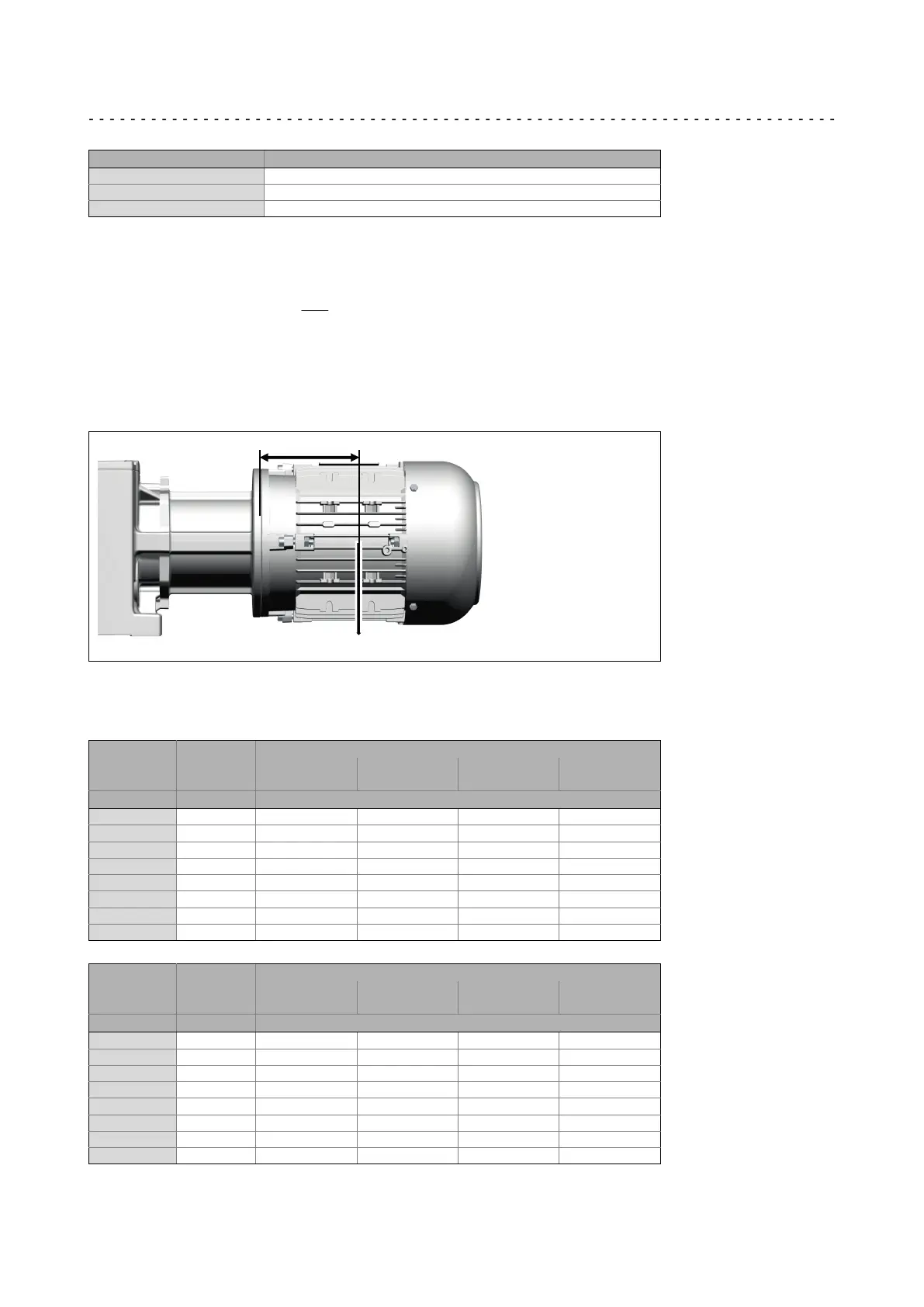
The position of the motor‘s centre of gravity, including all motor options, must be
calculated. If the distance of the centre of gravity L
Tab
is greater, the permissible force
must be reduced as follows.
F
Mperm
+ k
kloading
case
@ F
MTab
@
L
Tab
L
v k
kloading
case
@ F
MTab
If forces act from several directions, e.g. in the case of a moving horizontal travelling
drive, the acting forces have to be added vectorially (e.g. vertical force due to weight plus
horizontal acceleration force).
F
Mperm
corresponds to the maximum value of the forces added vectorially!
L
F
M
If the permissible force F
Mperm
is exceeded, the motor has to be supported in a suitable,
distortion−free fashion!
Drive size Distance L
Tab
of the motor
Gearbox type
S130
G50BS113
S220
G50BS122
S400
G50BS140
S660
G50BS166
[−] [mm] Maximum permissible force F
M
Tab
[N]
1A / 2B 80 350 350 350 350
1B 80 550 600 800 800
xC 115 550 600 800 800
xD 115 550 800 1000 1300
xE 145 −−−−− 800 1000 1300
xF 145 −−−−− −−−−− −−−−− −−−−−
xG 190 −−−−− −−−−− −−−−− −−−−−
xH 250 −−−−− −−−−− −−−−− −−−−−
Drive size Distance L
Tab
of the motor
Gearbox type
S950
G50BS195
S2100
G50BS221
S3100
G50BS231
S4500
G50BS245
[−] [mm] Maximum permissible force F
M
Tab
[N]
1A / 2B 80 −−−−− −−−−− −−−−− −−−−−
1B 80 800 800 800 −−−−−
xC 115 800 800 800 1500
xD 115 1500 1500 1500 1500
xE 145 1500 1500 1500 1500
xF 145 1500 1500 1500 1500
xG 190 1700 1700 1700 1700
xH 250 −−−−− 2600 3500 3500
 Loading...