Mechanical installation
Preparation
Attachment of gearboxes with hollow shafts and keyway
4
30
Lenze ¯ MA 12.0013 ¯ 3.0
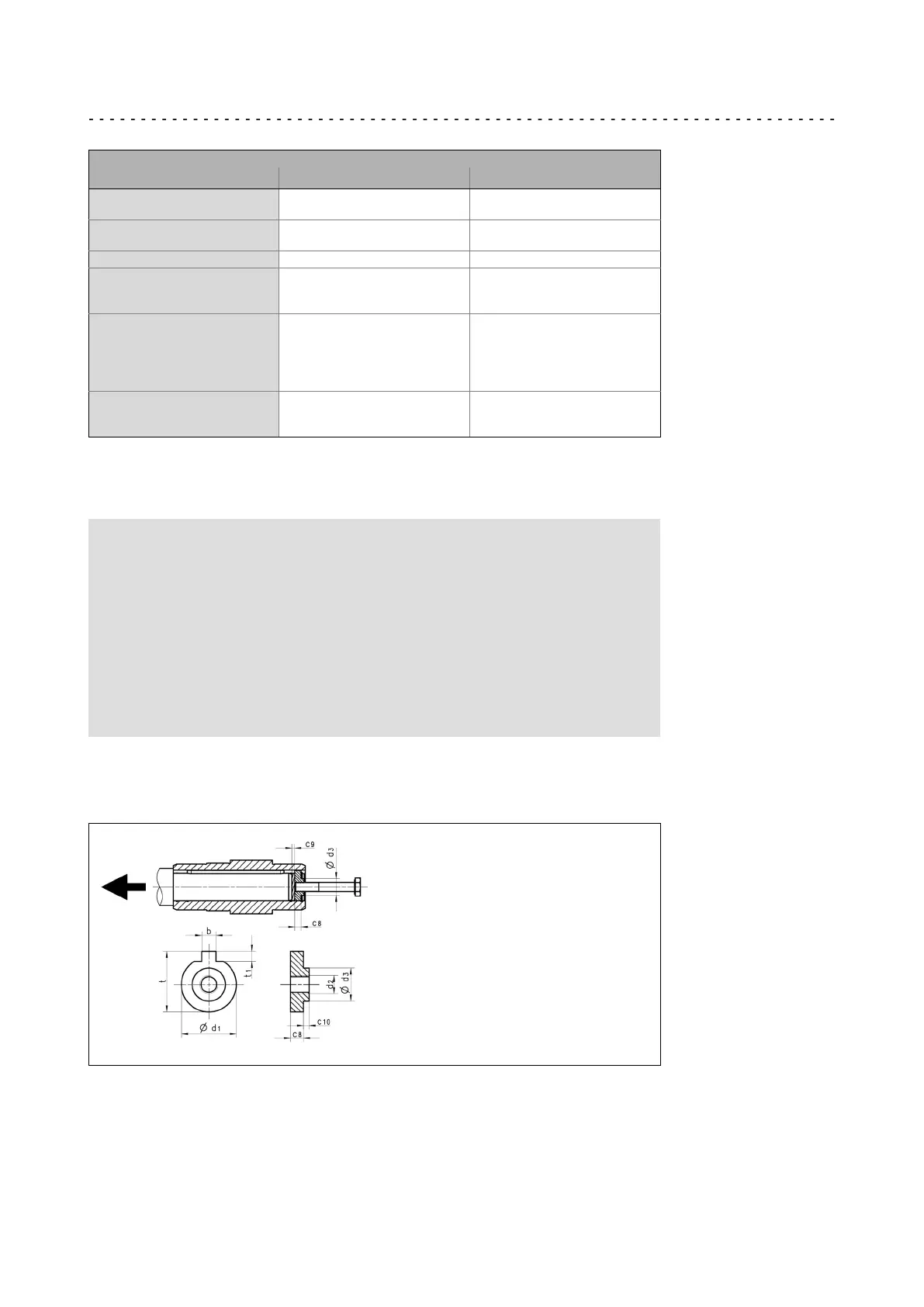
Auxiliary tool (recommended dimensions)
Æ d
H7
d
2
c
7
18
20
M6 4
25
30
M10
5
6
35 M12 7
40
45
50
M16
8
9
10
55
60
65
70
80
M20
11
13
13
14
16
90
100
120
M24
20
24
24
Tab. 4 Dimensions in [mm]
Dismounting
Stop!
¯ Before dismantling the machine shaft, mount an adequately
dimensioned load handling device at the gearbox.
¯ Ensure pretensioning of the drive mechanism, preventing the gearbox
from falling into the drive mechanism when it is loosened from the
plug−in shaft.
¯ When removing the hollow shaft via the housing, impermissibly great
forces may be generated.
¯ Tensioning of the hollow shaft causes a bearing failure and damage of
the gearbox housing.
1. Undo axial gearbox locking in the hollow shaft.
2. Remove/extract the gearbox from the motor shaft using an appropriate auxiliary
tool (LEERER MERKER).
Fig. 5 Disassembly of gearboxes with hollow shaft, with auxiliary tool
 Loading...