Mechanical installation
Preparation
Mounting the shrink disc with a rotating cover
4
31
Lenze ¯ MA 12.0013 ¯ 3.0
Auxiliary tool (recommended dimensions)
Æ d
H7
b ±0.1 c
8
c
9
c
10
d
1
±0.1 d
2
d
3
t −0.1 t
1
25 7.8 10 3 −−− 24.8 M10 −−− 28 5.5
30
7.8 10 3 −−− 29.8 M10 −−− 33 5.5
35
9.8 12 3 −−− 34.8 M12 −−− 38 6
40 11.8 12 4 −−− 39.8 M16 −−− 43 6
45 13.8 12 4 −−− 44.8 M16 −−− 48.5 7
50 13.8 12 5 −−− 49.8 M16 −−− 53.5 7
55 15.8 16 5 −−− 54.8 M20 −−− 59 7.5
60 17.8 16 5 −−− 59.8 M20 −−− 64.1 8
70 19.8 16 5 −−− 69.8 M20 −−− 74.1 8
80 21.8 20 5 −−− 79.8 M20 −−− 85.1 9
Tab. 5 Dimensions in mm
Note!
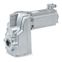
In the case of the shaft−mounted helical gearbox, the hollow shafts are
released to rotate freely in the central part, i.e. the hole diameter is
greater by 0.1 mm in this area! Provide for a sufficient length of the
machine shaft so that the machine shaft is guided on both sides.
Gearbox
l
1
min l
2
l max.
Code Type
G50BS113 g500−S130 75 35 104
G50BS122 g500−S220 91 40 120
G50BS140 g500−S400 117 50 150
G50BS166 g500−S660 133 57 170
G50BS195 g500−S950 143 60 180
G50BS221 g500−S2100 163 70 210
G50BS231 g500−S3100 188 80 240
G50BS245 g500−S4500 234 100 300
G50BS280 g500−S8000 260 135 350
G50BS314 g500−S14000 310 150 410
G50BS319 g500−S19000 380 180 500
Tab. 6 Dimensions in mm
4.3.9 Mounting the shrink disc with a rotating cover
Stop!
¯ Do not disassemble new shrink disc.
¯ Never tighten clamping screws before the machine shaft has been
inserted, since otherwise the hollow shaft may undergo plastic
deformation.
¯ During operation, the shrink disc has to be covered so that it is safe
against contact by implementing suitable measures (e.g. cover).
¯ Degrease hollow shaft bore and machine shaft!
 Loading...