Operating instructions i550 cabinet frequency inverter | 14
© 11/2021 · EN · www.Lenze.com
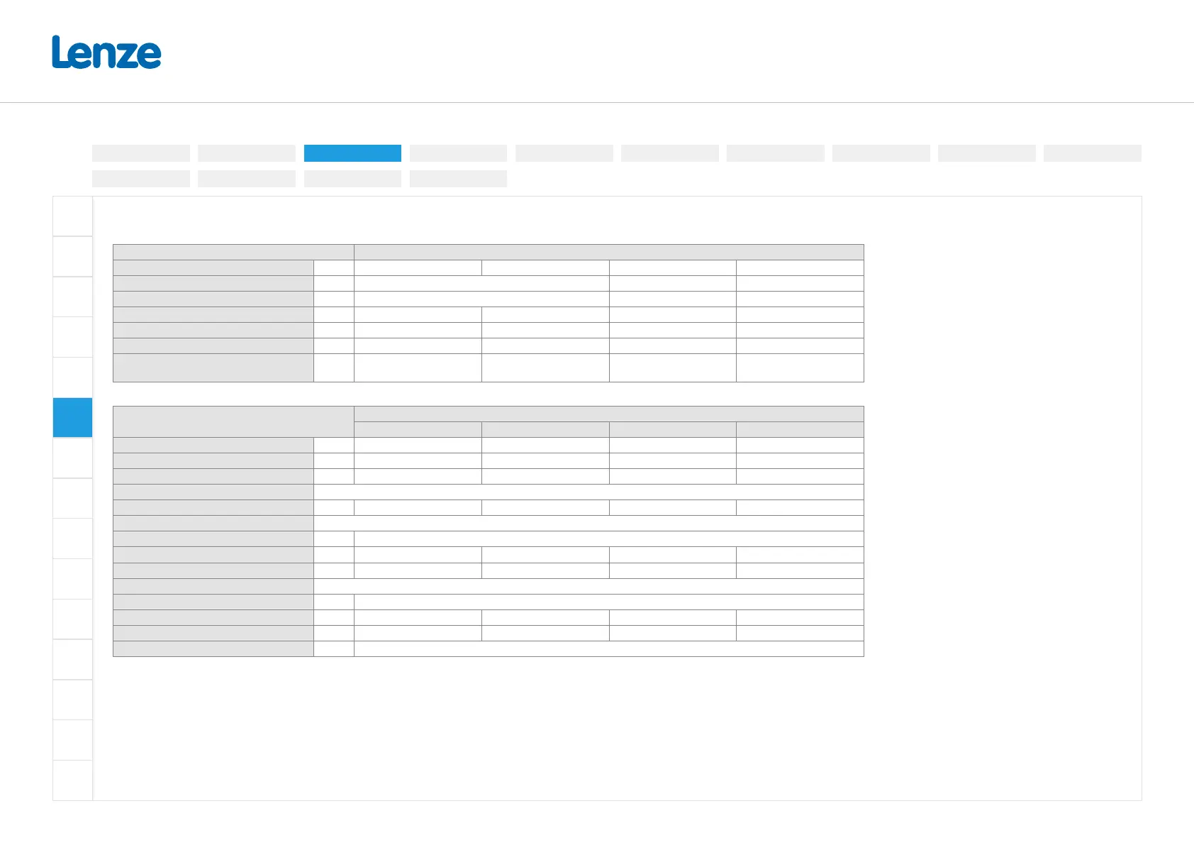
1-phase mains connection 120V (90 V ... 132 V, 45 Hz ... 65 Hz)
Terminal data
Inverter I55AExxxA
Rated power kW 0.25 ... 0.37 0.75 ... 1.1 0.25 ... 1.1 0.25 ... 1.1
Connection Mains connection X100 PE connection Motor connection X105
Connection type Screw terminal Screw Screw terminal
Max. cable cross-section mm² 2.5 6 6 2.5
Stripping length mm 8 8 10 8
Tightening torque Nm 0.5 0.7 2 0.5
Required tool
0.5 x 3.0
0.6 x 3.5
TX20
0.5 x 3.0
Rated data and fusing data
Inverter
I55AE
125A 137A 175A 211A
Rated power kW 0.25 0.37 0.75 1.1
Rated output current (8 kHz) A 1.7 2.4 4.2 6
Max. output current * A 3.4 4.8 8.4 12
Operation without mains choke
Rated mains current A 6.8 9.6 16.8 22.9
Fuse
Characteristic gG/gL or gRL
Max. rated current A 16 16 32 32
Max. short circuit current (SCCR) kA 5 5 5 5
Circuit breaker
Characteristic B, C
Max. rated current A 16 16 32 32
Max. short circuit current (SCCR) kA 5 5 5 5
Residual current device (RCD) ≥ 30 mA, type B
* Overload time = 3s, recovery time = 12s
Electrical installation
3-phase | 480 V
3-phase | 230/240V
3-phase | 400 V1-phase | 120V
1-phase | 230/240V
Control terminals
Relay output
Connection diagram
Brake resistor
Networks
Functional safety
Safe torque o (STO)
PTC input
Preparation