10
Electrical installaon
Operang Instrucons i550-Cabinet
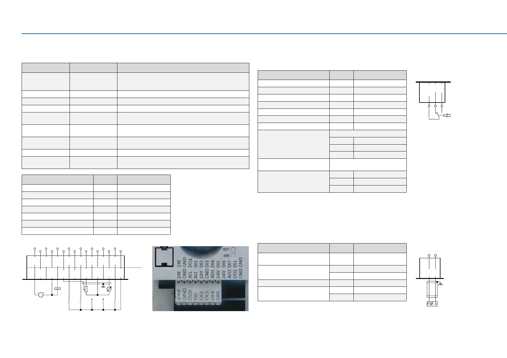
5.3 Control terminals
Standard I/O
Input/output Terminal X3 Informaon
Digital inputs DI1, DI2, DI3, DI4, DI5 DI3/DI4 can be oponally used as frequency or encoder input.
HIGH-acve/LOW-acve switchable LOW = 0 ... +3 V,
HIGH = +12 V ... +30 V
Digital outputs DO1 Digital output (max. 100 mA for DO1 and 24-V output)
Analog inputs AI1, AI2 Can be oponally used as voltage input or current input.
Analog outputs AO1 Can be oponally used as voltage output or current output.
24-V input 24E Input for mains-independent power DC supply of control electronics
(including communicaon). Max. 1 A
10-V output 10 V Primarily for the supply of a potenometer (1 ... 10 kΩ).
Max. 10 mA
24-V output 24 V Primarily for the supply of digital inputs. (Max. 100 mA for DO1
and 24-V output)
Reference potenal GND
Connecon system Pluggable spring
terminal
Inverter [kW] 0.25 ... 132
Connecon Control terminals X3
Connecon type Pluggable spring terminal
Min. cable cross-secon mm² -
Max. cable cross-secon mm² 1.5
Stripping length mm 9
Tightening torque Nm -
Tools required 0.4 x 2.5
Control terminals
DC 24 V SELV/PELV
(+19.2 … +28.8 V)
1k ... 10k
0 ... 10 V
S1
DI3 DI4
24E
AI1
AI2
10V
GND
AO1
24V
X3
GND
GND
24E
DO1
DI1
DI2
DI3
DI4
DI5
Front
row
Back
row
5.5 PTC input
In the default seng, the motor temperature monitoring is acve! By default, a wire jumper
is installed between the terminals T1 and T2.
Before connecng a thermal sensor, remove the wire jumper.
Inverter [kW] 0.25 ... 132
Connecon PTC or thermal contact
X109
Terminal X109: T1
Terminal X109: T2
Sensor types PTC single sensor
PTC triplet sensor
Thermal contact
5.4 Relay output
The relay is not suitable for direct switching of an electromechanical holding brake.
Use a corresponding suppressor circuit in case of an inducve or capacive load.
Inverter [kW] 0.25 ... 132
Connecon Relay output X9
Connecon type Pluggable screw terminal
Min. cable cross-secon mm² -
Max. cable cross-secon mm² 1.5
Stripping length mm 6
Tightening torque Nm 0.2
Tools required 0.4 x 2.5
COM Common contact
NC Normally-closed contact
NO Normally-open contact
Max. switching voltage/switching
current
AC 240 V/3 A
DC 24 V/2 A
DC 240 V/0.16 A
PTC input
X109
T1
T2
Relay output
NC
NO
COM
X9
AC 240 V
3 A
 Loading...


