Do you have a question about the Lenze SMV Series and is the answer not in the manual?
General safety precautions for handling and installing the frequency inverter.
Guidelines for safe and correct installation of the frequency inverter.
Information on safe use of the drive in various applications.
Operational safety, system monitoring, and understanding safety notifications.
Information regarding harmonic current emissions and compliance with EN standards.
Safety requirements related to EN 61800-5-1 and UL standards.
Details conformity, approvals, and environmental conditions for operation.
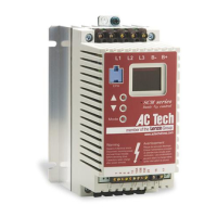
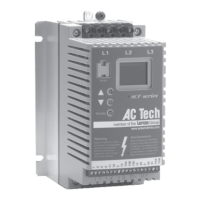
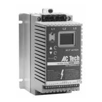
Lists SMVector Inverter models used in CaptiveAire systems.
Presents electrical and performance ratings for various voltage models.
Details electrical and performance ratings for 240V Three Phase and 400...480VAC models.
Details ratings for 600VAC models and notes on derating.
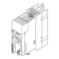
Provides physical dimensions and mounting details for NEMA 1 (IP31) models.
Details electrical installation steps, including long-term storage and power connections.
Guidance on connecting mains and motor power to the drive.
Diagrams for connecting mains and motor power supplies.
Details the control terminal connections and their descriptions.
Explains the functions of the local keypad, display, and buttons.
Details parameters for start source, reference, frequency, voltage, and overload.
Covers I/O configuration, advanced settings, and PID parameters.
Parameters for Vector control, network communication, and Modbus registers.
Overview of diagnostic parameters and Modbus register map.
Lists and explains status and warning messages, their causes, and remedies.
Explains the 4-digit codes indicating drive configuration and stop source.
Lists and explains common fault messages, their causes, and remedies.
| Category | DC Drives |
|---|---|
| Enclosure Rating | IP20 |
| Control Mode | V/Hz, Sensorless Vector Control |
| Communication Interfaces | CANopen |
| Protection Features | Overcurrent, Overvoltage, Undervoltage, Overtemperature, Short Circuit |
| Series | SMV |