SMVector I/O Module ALSV01 v1.0 13376253 10
Installation
3.3 Electrical Installation
3.3.1 Terminal Description
Table 3 contains each terminal's electrical specifi cation and any parameter description associated with
that terminal.
Table 3: Additional I/O Module Specifi cations
Terminal Function Description
19 Relay N.O. Relay output confi gurable with P441, P144
AC 250 V / 3 A 17 DC 24 V / 2 A … 240 V / 0.22 A, non-inductive
20 Relay Common
21 Relay N.C.
13F Digital Input 13F confi gurable with P426
13G confi gurable with P427
Input Impedance = 4.3 kohm
The assertion level of Terminals 13F and 13G will match the assertion level of the
standard SMVector digital inputs 13A, 13B, 13C, etc. Refer to the description of P120
and Terminal #4 in the SMVector - Frequency Inverter Operating Instructions (SV01)
13G Digital Input
NOTE
For ESVZAL0:
Control and communications terminals provide reinforced insulation when the drive is connected to a power system
rated up to 300V between phase to ground (PE) and the applied voltage on terminals 19, 20 and 21 is less than 250
VAC between phase and ground (PE)
For ESVZAL1:
Control and communications terminals provide reinforced insulation when the drive is connected to a power system
rated up to 300V between phase to ground (PE) and the applied voltage on terminals 19, 20 and 21 is less than 150
VAC between phase and ground (PE)
Control and communications terminals provide basic insulation when the drive is connected to a power system
rated up to 300V between phase to ground (PE) and the applied voltage on terminals 19, 20 and 21 is less than 250
VAC between phase and ground (PE).
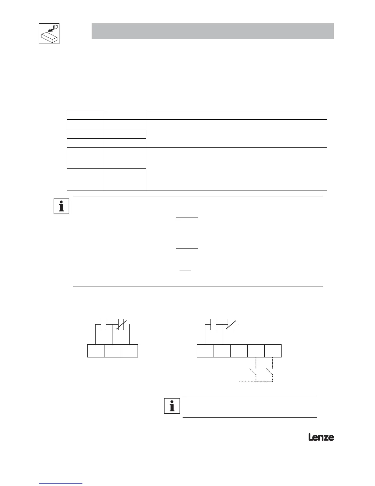
3.3.2 Module Wiring
Figure 5 illustrates the wiring of the ESVZAL0 and ESVZAL1 modules.
19 20
21
19 20
21
13F
13G
To SMVector Control
Terminal Stri
TB#4
Figure 5a: ESVZAL0 Figure 5b: ESVZAL1
NOTE
To assert terminals 13F and 13G with external power sources, refer
to section 3.2.3 of the SMVector Operating Instructions (SV01)