14 Friedrich Leutert GmbH & Co. KG
Engine Indicators Type 50 and Type 30 - Operating Instructions
Blow through the connection line before mounting the indicator to
prevent wrong indication of the engine pressure by any condensed
water, oil or soot deposits in the connection line.
DANGER: The valve ejects hot gas under high pressure. Danger
of sparks and burning!
Close the indicator valve.
Pull the cord to draw the atmospheric pressure line.
If necessary, the atmospheric pressure line of the diagram can be
raised by placing one or more washers (must be ordered separately)
on the spring support before mounting the spring.
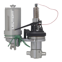
Screw the indicator onto the indicator valve.
WARNING: Use the hollow spanner only to screw the indicator
on or off the indicator valve. Hammering on the extensions of
the connecting nut will damage the nut. As a result of these
damages the nut might break apart under the influence of the
high pressure and the indicator may be propelled through the
engine room with great speed.
The indicator should be mounted preferably near to the engine
cylinder to be tested. If the indicator connections are arranged at
the side of the engine cylinder, the indicator will be in a horizontal
position. This will not effect the functionality of the indicator. In
some cases extension tubes are required to fit the indicator.
Open the indicator valve fully.
WARNING: Danger of injury during the measuring procedure
caused by moving parts such as indicator spring, piston rod,
drum cylinder and recording lever.
Pull the indicator cord.
Close the indicator valve.
Remove the indicator cord from the drum and verify the result. The
procedure can be repeated.
CAUTION: If testing internal combustion engines, piston and
piston rod of the indicator should be lubricated periodically
after 10 to 15 diagrams.
 Loading...