Do you have a question about the Leuze electronic MSI 400 and is the answer not in the manual?
Defines the necessary qualifications and training for personnel working with the MSI 400.
Provides essential safety guidelines, legal regulations, and protective measures.
Describes the MSI 410 controller, its versions, display elements, and terminal assignment.
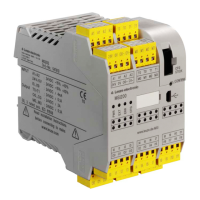
Describes the MSI 420 controller, its versions, display elements, and terminal assignment.
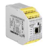
Describes the MSI 430 controller, its gateway functions, and display elements.
Details the procedure and precautions for installing modules on a 35mm hat rail.
Describes the procedure for safely removing controller and expansion modules from the hat rail.
Outlines electrical installation requirements, safety standards, and important notes.
Provides information on required software and storage for system configuration.
Details the steps for total acceptance inspection and validation of the system.
Describes pre-commissioning tests to confirm safety requirements and operator training.
Provides guidance on handling system errors and conducting post-error function tests.
Explains different error levels (Configuration, Repairable, Critical) and recovery steps.
Covers error codes, causes, and measures for error resolution via LEDs and software.
Details LED indicators and their meanings on MSI 4xx controller modules for diagnostics.
Explains LED indicators for MSI-EM-IO84 and MSI-EM-I8 safe input/output modules.
Explains LED indicators for MSI-EM-IO84NP standard input/output modules.
Outlines procedures for regular testing and inspection of safety equipment.
Discusses replacing faulty MSI 400 modules and re-establishing network operation.
| Type | MSI 400 |
|---|---|
| Housing material | Plastic |
| Product category | Accessories |
| Operating voltage | 24 V DC |
| Ambient temperature | 0 to 55 °C |
| Storage temperature | -20°C to +70°C |
| Connection | Pluggable screw terminal |
| Weight | 200 g |