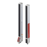
The CML 720i is a configurable, multi-sensor measuring light curtain designed for object detection and measurement in various industrial applications, including handling and warehousing systems, and the packaging industry. The complete system comprises a transmitter and a receiver, connected by a synchronization cable. The receiver features an integrated control panel with indicators and operational controls for configuration. Power is supplied via connection X1 on the receiver.
Function Description
The CML 720i series offers a variety of beam modes and evaluation functions to adapt to different application and operating conditions.
Beam Modes:
- Parallel-beam scanning: Each transmitter LED's light beam is detected by the directly opposing receiver LED.
- Diagonal-beam scanning: Each transmitter diode's light beam is received by both the directly opposing receiver diode and the next receiver diode in the counting direction (i-1). This increases resolution in the central area. The number of beams for diagonal-beam scanning is calculated as
nd = 2np - 1, where np is the number of beams for parallel-beam scanning.
- Crossed-beam scanning: Each transmitter LED's light beam is detected by the directly opposing receiver LED and the two adjacent receiver LEDs (i+1, i-1), further increasing resolution in the measurement field. The number of beams for crossed-beam scanning is calculated as
nk = 3np - 2.
Measurement Beam Sequence:
By default, counting begins at the sensor connection unit, but it can be reconfigured to start at the sensor head. This allows for flexible mounting, such as vertical mounting with the connection unit at the top for height measurement, or for width detection where counting can begin at either end of the sensor head.
Evaluation Functions:
The device evaluates individual optical beam states (free/interrupted) and provides results through various functions:
- TIB (Total Interrupted Beams): Counts all interrupted beams.
- TNIB (Total Not Interrupted Beams): Counts all not interrupted beams.
- LIB (Last Interrupted Beam): Identifies the last interrupted beam.
- LNIB (Last Not Interrupted Beam): Identifies the last not interrupted beam.
- FIB (First Interrupted Beam): Identifies the first interrupted beam.
- FNIB (First Not Interrupted Beam): Identifies the first not interrupted beam.
- Beam-stream: Returns the status of each individual beam, with uninterrupted beams represented as logical 1.
- Status of beam areas 1...32: Provides status for up to 32 defined beam areas.
- Status of digital inputs/outputs: Indicates the logical state of digital I/Os.
Hold Function:
This function temporarily stores the minima and maxima of evaluation functions (FIB, FNIB, LIB, LNIB, TIB, TNIB, and beam-stream) for an adjustable period. This simplifies reading measurement results, especially if the control system cannot process data at the same speed as the light curtain provides it.
Blanking:
Unnecessary beams can be suppressed if continuously interrupted by existing frames or crossbars. This ensures these beams are not included in the evaluation, without affecting beam numbering. Up to four adjacent beam areas can be suppressed, and their behavior (logical 0, logical 1, or behaving like an adjacent beam) can be configured. Auto blanking during teaching allows interrupted beams to be mapped to blanking areas, overwriting existing settings.
Power-Up Teach:
After applying operating voltage, this function performs a teach event when the device is ready for operation. If successful, new teach values are adopted; otherwise, previously saved values are used. This function can only be activated via the receiver control panel.
Smoothing:
The smoothing function ensures that interrupted beams are only considered in the evaluation if a set minimum number of adjacent beams are simultaneously interrupted. This helps suppress interference from spot soiling on the lens cover. Inverted smoothing can suppress interference near object edges by not evaluating uninterrupted beams until a set number is reached, useful for detecting successive openings in web material.
Cascading/Triggering:
Multiple light curtains can be cascaded in series to extend the measurement path, preventing mutual interference through time-offset activation (triggering). This is achieved via internal or external trigger signals.
- External triggering: A pulse at the trigger input starts the measurement cycle, allowing different delay times for cascaded light curtains.
- Internal triggering: A CML 700i configured as a "master light curtain" generates a continuous trigger pulse, eliminating the need for a primary control activation.
Block Evaluation of Beam Areas:
This function reduces the quantity of data transmitted by restricting imaging accuracy while retaining minimum resolution. Up to 32 beam areas can be defined, and their individual beam information is linked to a logical bit.
- Autosplitting: Automatically divides beams into a selected number of areas of the same size.
- Mapping beam area to switching output: Allows signaling the state of any number of adjacent beams (area) at a switching output, useful for trigger signals, object detection, or reference checks.
- Teach height area: Configures up to four height areas for applications like height monitoring or sorting. An object is used to automatically define a height area, combining free beams above or below it.
Switching Outputs:
The behavior of switching outputs (Q1 to Q4 or Q1 to Q2) can be configured for light/dark switching. Various time functions (start-up delay, switch-off delay, pulse stretching, pulse suppression) can be assigned to individual switching outputs.
Interference Suppression (Filter Depth):
To suppress faulty measurement values caused by interference (ambient light, electromagnetic fields), the filter depth can be increased. A beam state change is only included in data evaluation if it remains stable for the set number of measurement cycles.
Important Technical Specifications:
- Operating range: Up to 7000 mm.
- Measurement field length: 150 mm to 2960 mm.
- Beam spacings: 5 mm, 10 mm, 20 mm, 40 mm.
- Response time: 30 µs per beam.
- Resolution: Minimum object size reliably detected. For parallel-beam, it's the sum of beam spacing and optic diameter.
- Interfaces:
- IO-Link: 4 digital inputs/outputs (configurable), 2 analog current/voltage outputs.
- CANopen, PROFIBUS-DP, RS 485 Modbus, PROFINET: 2 digital inputs/outputs (configurable) plus IO-Link.
- Electrical supply: 18...30 VDC.
- Current consumption: Varies with measurement field length, e.g., 135 mA at 160 mm (24 VDC) to 350 mA at 1440 mm (24 VDC).
- Switching output current: Max. 100 mA.
- Activation delay: ≤ 1 ms.
- Housing: Continuous-cast aluminum.
- Optics cover: PMMA plastic.
- Connection technology: M12 connectors (8-pin/5-pin).
- Ambient temperature (operation): -30 °C to +60 °C.
- Degree of protection: IP 65.
- Protection class: III.
- Light source: 940 nm infrared LED (exempt group in accordance with EN 62471).
- Electromagnetic compatibility: IEC 61000-6-2 and EN 1000-6-4 (Industrial interference emission, Class A product).
Usage Features:
- Local control panel with display: For basic configuration, alignment, and process monitoring. The OLED display shows alignment status (bar graphs for first and last beams) or process mode (total interrupted beams and digital output states).
- Sensor Studio configuration software: Provides a graphical user interface for advanced configuration, diagnosis, and operation via a PC and IO-Link USB master.
- Language selection: English, German, French, Italian, Spanish.
- Display properties: Configurable visibility (Off, Dark, Normal, Bright, Dynamic) and display duration.
- Product information: Access to part number, serial number, firmware/hardware versions.
- Reset to factory settings: Option to restore default configurations.
Maintenance Features:
- Cleaning: The sensor can be cleaned with a soft cloth and commercially available glass cleaner to remove dust. Aggressive cleaning agents like thinner or acetone should be avoided to prevent damage to the lens cover.
- Protective film: An optional protective film (PT 20-CL3500) is available to shield the lens cover from dust and liquids. Soiled films can be easily removed and replaced.
- Servicing: Repairs should only be performed by Leuze electronic GmbH + Co. KG. Contact customer service for support or firmware updates.
- Disposal: Observe applicable national regulations for electronic component disposal.