Electrical connection
Leuze electronic GmbH + Co. KG CML 720i 56
7.5.3 X2/X3 pin assignment – CML 700i with IO-Link/analog interface
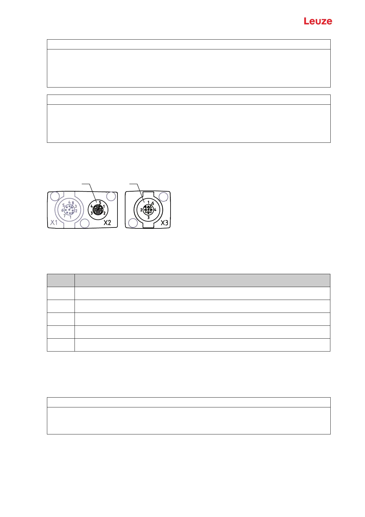
5-pin, M12 socket/connector (A-coded) for the connection between transmitter and receiver.
1 M12 socket X2 (5-pin, A-coded)
2 M12 connector X3 (5-pin, A-coded)
Figure 7.8: X2/X3 connection – CML 700i with IO-Link/analog interface
Table 7.4: X2/X3 pin assignment – CML 700i with IO-Link/analog interface
Interconnection cables: see table 21.4.
7.6 Electrical connection – CML 700i with CANopen, PROFIBUS and RS 485 Modbus interface
The electrical connection is established in the same way for all devices with CANopen, PROFIBUS and
RS 485 Modbus interfaces.
NOTICE
Signal crosstalk in analog operation during simultaneous IO-Link communication!
If the simultaneous operation of IO-Link and analog signals is desired, perform the following measures:
Wire a filter to the analog input of the control.
Use shielded cables for the analog lines.
NOTICE
Permissible load resistance on the analog output!
When connecting the analog output, note the permissible load resistance.
Voltage output 0 … 10 V DC / 0 … 11 V DC: R
L
≥ 2 k Ω
Current output 4 … 20 mA DC / 0 … 24 mA DC: R
L
≤ 500 Ω
1 2
Pin X2/X3 - Transmitter and receiver
1 SHD: FE functional earth, shield
2 VIN: +24 V DC supply voltage
3 GND: ground (0 V)
4 RS 485 Tx+: synchronization
5 RS 485 Tx-: synchronization
NOTICE
Light curtain grounding!
Ground the light curtain before establishing an electrical connection or connecting the voltage supply
(see chapter "Grounding the light curtain housings").


 To Next Page