Starting up the device - Basic configuration
Leuze electronic GmbH + Co. KG CML 720i 73
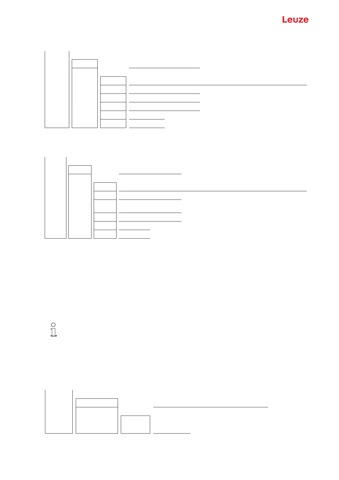
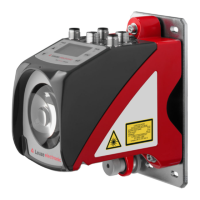
Select Digital IOs > IO Pin 2 > Inversion > Inverted.
8.5.3 Defining the filter depth
The filter depth is used to specify that an evaluation and output of the measurement values occurs only
once the beam states are stable over multiple measurement cycles.
Example: with a filter depth of “5”, five measurement cycles must be consistent before an evaluation is
performed. For further information, see also the description of interference suppression (see
chapter 4.12).
The structure of the configuration in the receiver control panel menu is as follows:
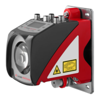
Select Main Settings > Operation Settings > Filter Depth.
Level 0 Level 1 Level 2 Description
Digital IOs
IO Logic Positive PNP Negative NPN
IO Pin 2
IO function Trigger In Teach In Area Out Warn Out Trigger Out
Inversion Normal Inverted
Teach height Execute Exit
Area logic AND OR
Start beam (enter value)
End beam (enter value)
Level 0 Level 1 Level 2 Description
Digital IOs
IO Logic Positive PNP Negative NPN
IO Pin 2
IO function Trigger In Teach In Area Out Warn Out Trigger Out Validation Out
Inversion Normal Inverted
Teach
height
Execute Exit
Area logic AND OR
Start beam (enter value)
End beam (enter value)
For all digital process interfaces, the configuration can also be performed via the respective field-
bus interface (see chapter 10 et seq.) or via the
Sensor Studio
configuration software (see
chapter 16).
When configuring the filter depth, you can enter values of up to 255. Values above 255 (to 299)
are not accepted and must be entered again.
Level 0 Level 1 Level 2 Description
Main Settings
Commands Teach Reset Factory settings
Operation settings
Filter Depth (enter value)
min = 1
max = 255


 To Next Page